Computed Tomography (CT) Protocol Guidlines
1 Scope
For local use within the CT scanning department.
2 Purpose
To ensure the best possible imaging for all CT examinations.
3 Definition of terms
Staging
In the context of this document refers to the follow-up of known cancers on a treatment pathway. ?
Any request to investigate a new diagnosis of cancer will be marked as ‘Query’ (?) in the protocol description.
Early Arterial 10 seconds delay from the point of trigger
Late Arterial 23 seconds delay from the point of trigger. Some protocols will have a ‘fudge factor’ built-in to allow the chest to be scanned prior to the abdomen, keeping the abdomen in the late arterial phase. BW
Body Weight contrast volume 2 or 4 dose
Oral preparation, 5 mL Omnipaque 300 in 250mL of water
Chest
Apices of the lungs to costophrenic angles
Chest and Abdomen
Apices of the lungs to iliac crests
Abdomen
Dome of diaphragm to iliac crests
Abdomen and Pelvis
Dome of diaphragm to lesser trochanters
Chest, Abdomen and Pelvis
Apices of the lungs to lesser trochanters
Neck, Chest, Abdomen and Pelvis
Base of skull to lesser trochanters
Gated Study
Scanning with ECG electrodes to acquire images according to a set percentage of the patients R-R cardiac cycle
Thoracic Aorta
Apices to costophrenic angles
Abdominal Aorta
Dome of diaphragm to iliac crest
Whole Aorta
Apices of the lungs to lesser trochanters
Bastion
Single Acquisition, multi-dose contrast delivery ROI
Region of interest GG
Gastrograffin
4 Introduction
CT scanning procedures administer a particularly high dose of ionising radiation
to the patient. It is of paramount importance and part of the IR(ME)R guidelines
that patient radiation dose is kept to a minimum. To ensure this is adhered to, and that the type/dosage of contrast medium and acquisition timings are optimised to detect the pathologies of concern, a list of protocols have been created. This document also serves as an educational tool for the training of radiologists and radiographers.
5 Responsibilities
Radiologists
Ensuring that the CT protocols are up to date and adhered to, ensuring the correct protocol is requested on the relevant Epic request when vetting and provide relevant scanning information as required.
Radiographers
Carrying out the correct scan following the CT protocols Ensuring the correct protocol is requested on the relevant Epic request when vetting and provide relevant scanning information as required. Review resultant images and perform additional scans/recons/injections of contrast media relevant to any found pathology. Seek Consultant Radiologist/Senior SpR Radiologists opinion when necessary.
6 Weight-Based contrast
In most protocols, the volume of contrast medium to be administered will be based on bodyweight (BW) at a dose of 540 mg/kg . Exceptions are highlighted.
Rates of injection are to be those as per the chart in Appendix 1 . Omnipaque 350 is preferred in order to reduce injection times and flow rate. A maximum dose of 200mL is stated, although there are no published guidelines in this regard. A risk/benefit analysis should be performed on a case-by-case basis if a study is non-diagnostic or inadequate: if necessary, a study may be repeated with additional contrast medium following discussion with the clinical team in charge as appropriate. Periprocedural hydration may be considered.
Preparations are administered by CT administrative staff unless stated otherwise.
Scope ............................................................................................................................ 2
Purpose ......................................................................................................................... 3
Definition of terms.......................................................................................................... 4
Introduction .................................................................................................................... 5
Responsibilities ............................................................................................................. 6
Weight-Based contrast .................................................................................................. 7
Table of Contents .......................................................................................................... 8
Chest Protocols ........................................................................................................... 10
Abdomen & Pelvis Protocols ....................................................................................... 14
9.1
CT Oral Contrast Protocol – Preparation Guidance............................................... 15
9.2
GI Tract Protocols .................................................................................................. 16
9.3
Colonography Protocols ........................................................................................ 18
9.4
Adrenal, Endocrine, Lymphatic System Protocols ................................................. 20
9.5
Hepatobiliary (HPB) Protocols ............................................................................... 22
9.6
Pancreas Protocols ............................................................................................... 25
9.7
Urology and Gynae Protocols ................................................................................ 26
9.8
Miscellaneous ........................................................................................................ 29
9.9
Vascular Protocols ................................................................................................. 30
9.10
Muscular-Skeletal (MSK) .................................................................................... 35
Trauma – Adult ......................................................................................................... 37
10.1
Trauma East Manual of Proceedures and Operations (TEMPO) Guidelines ..... 38
Paediatrics ................................................................................................................ 40
11.1
Paediatric general/oncology scanning protocols ................................................ 41
Paediatric Trauma .................................................................................................... 45
12.1
CT Paediatric Trauma scanning parameters by weight: ..................................... 47
Neuro Protocols ........................................................................................................ 49
13.1
Standard Head Protocols ................................................................................... 50
13.2
Operative Navigation (Stealth) ........................................................................... 53
13.3
Facial Imaging .................................................................................................... 55
13.4
Temporal Bones ................................................................................................. 57
13.5
Spine .................................................................................................................. 59
13.6
Neck ................................................................................................................... 62
13.7
Vascular ............................................................................................................. 64
13.8
Neuro Intervention .............................................................................................. 66
13.9
Specialist Scanning ............................................................................................ 68
13.10
Standard Paediatric Head Protocols .................................................................. 70
13.11
Operative Navigation (Paediatric Stealth) .......................................................... 72
13.12
Standard Paediatric Spine Protocols .................................................................. 74
13.13
Standard Paediatric Crainofacial Protocols ........................................................ 76
13.14
Standard Paediatric Vascular Protocols ............................................................. 79
Paediatric Sedation and Vascular Access ................................................................ 81
14.1
Sedation ............................................................................................................. 82
14.2
Intravenous Contrast Administration for Paediatric Patients .............................. 83
References ............................................................................................................... 84
Associated documents .............................................................................................. 85
Appendix 1 Contrast, Dose & Injection Rates vs Bodyweight ............................................ 86
Appendix 2 DIEP Post-Processing Reconstruction Guide .................................................. 88
Appendix 3 CT Thoracic Aorta aneurysm surveillance protocolling flow chart .................... 89
Appendix 4 CT AAA surveillance protocolling flow chart .................................................... 90
Appendix 5 Bilateral Arm Injection Guide .......................................................................... 91
Appendix 6 CT Enterography Proceedure .......................................................................... 92
Appendix 7 Orthopaedic Reconstruction of Pelvic & Hip Fractures .................................... 93
Appendix 8 Skeletal Survey Protocol .................................................................................. 94
Appendix 9 CTC Protocolling Flow Chart ........................................................................... 95
Appendix 10 CTC After Intervention at Coloscopy Policy ................................................... 96
Appendix 11 CT Head Imaging Technique ......................................................................... 97
Appendix 12 Dementia Reformats .................................................................................... 102
Appendix 13 Brain Perfusion Maps .................................................................................. 105
Appendix 14 Max-Fax Facial Bones and Mandible reconstruction ................................... 112
Appendix 15 Sinus Reformats .......................................................................................... 116
Appendix 16 Spine Reformats .......................................................................................... 118
Appendix 17 Orbit Reformats ........................................................................................... 119
Appendix 18 Vasospasm Imaging .................................................................................... 122
Appendix 19 Temporal Bone Reformats ........................................................................... 127
Appendix 20 Cerebral Venography ................................................................................... 128
8 Chest Protocols
2WW Lung Cancer Referrals
The following is a general guide for Band 7 Radiographers vetting 2WW Cancer Pathway CT Chest referrals from the Lung Cancer
Specialist team.
If unsure, requests are to be vetted by a Consultant Thoracic Radiologist.
Normal CXR
Unenhanced chest only If definite haemoptysis = Arterial chest (25 sec delay)
Abnormal CXR
Arterial chest and portal venous abdomen o If specific pelvic bony symptoms then include contrast pelvis
o If appears metastatic disease in chest (or known malignancy elsewhere) then include contrast pelvis
Protocol
Prep
IV
Imaging
Timing
Notes
Bronchiectasis, Interstitial fibrosis, Emphysema, COPD,
Vasculitis, Sarcoid, Small airways disease, Bronchiolitis, Asthma
Protocol name: Chest_NonContrast
Non-contrast Chest
? Lung Cancer
Lung Cancer Staging/Follow-up
Mediastinal Mass/Anatomy
Protocol name: ChestAbdo_LungCa_Contrast
BW Arterial Chest Portal Abdomen 25s 70s
Empyema
Protocol name: Chest_Contrast
BW Arterial Chest 25s
Malignant pleural disease
Pleural Thickening
Mesothelioma
Protocol name: ChestAbdo_Portal
BW Portal Chest and Abdomen (one run) 70s ? Interstitial lung disease (ILD) / Bronchiectasis
Protocol name: Chest_NonContrast
Non-contrast chest
Shortness of breath post Stem Cell / Organ Transplant
Hypersensitive Pneumonitis
Rheumatoid Arthritis (RA)
Protocol name: Chest_Exps
Non-contrast chest Sequential Expiration Scans of the chest (1’s on 10mm)
? PE / Haemoptysis / Dyspnoea
Protocol name: PE_Scan
If abdomen and Pelvis required:
Protocol name: PE_AbdoPelvis
kV Dependant 5ml/Sec Chest Bolus tracked at the level of the carina. ROI to be placed on pulmonary artery.
Contrast Volumes:
80kV = 40mL 100kV = 60mL 120kV = 80mL
If scanning AbdoPelvis use BW contrast dose ? Asbestosis ? Drug Reaction
Protocol name: Chest_NonContrast
Chest Prone -
Send images as scanned (do not flip and mirror)
Oesophageal Ca Staging / follow-up
Protocol name: ChestAbdo_LateArterial
H 2 O BW Late arterial Chest and Abdomen (To include Supraclavicular fossa) Portal Abdomen & Pelvis Bolus-tracked late arterial 70s
Triggered off abdominal Aorta at the level of the diaphragm
Oesophageal Perforation
Suspected Iatrogenic Perforation (e.g. post-surgery/endoscopy)
Protocol: Chest_NonContrast + ChestAbdo_LateArterial
BW Unenhanced Chest/Abdo (i.e. Pre oral / IV) On table – give 200-300 ml 10% water soluble low Osmolar contrast medium (e.g. Omnipaque). Late arterial Chest & Abdomen Portal Abdomen & Pelvis
Oral Contrast
Bolus-tracked late arterial 70s
Suspected Spontaneous Oesophageal Perforation
Protocol: ChestAbdo_LateArterial
BW Late arterial Chest & Abdomen Portal Abdomen & Pelvis
Bolus-tracked late arterial 70s
No oral contrast medium or unenhanced required ? Thymoma / Graves’ Disease / Goitre
Protocol Name: ENT_NeckChest
70mL ENT Neck and Chest protocol 80s – Neck
Chest scanned shortly after
Separate body regions into correct accession numbers.
Scan with arms down
Lung nodule (Size check)
Protocol name: Chest_LowDose
Low dose Chest
Ground Glass Nodule
Protocol name: Chest_NonContrast
Chest
Breast Ca Staging and Follow Up
Protocol name: CAP_Portal
BW Portal Chest, Abdomen and Pelvis (One run) (To include supraclavicular fossa to below lesser trochanter) 70s
Large Airways
Protocol name: Chest_NonContrast
+ Append another Chest_NonContrast
(1) Chest Inspiratory (2) Expiration from vocal cords to below carina
No longer need to instruct patient to breathe out slowly for duration of scan. Follow standard expiration instructions.
Fungal Chest / Infection
Protocol name: Chest_NonContrast
Chest
Mediastinal abnormality Assessment
Acute bleeding (e.g. haemoptysis)
Mediastinal Lymph Nodes Assessment (e.g. TB, sarcoid, malignancy)
Protocol name: Chest_Contrast
BW Chest 25s
Tracheobronchomalacia (TBM)
Protocol Name: Chest_NonContrast
Non Contrast Chest Dynamic Expiration from vocal cords to just below carina
Inspiration
Non contrast dynamic exps
(Volume NOT
Sequential)
Remove breathing instructions and ask patient to slowly breath out for the duration of the scan
Abdomen & Pelvis Protocols
9.1
CT Oral Contrast Protocol – Preparation Guidance
5mL of Omnipaque 300™ (Iohexol) mixed with approximately 250mL of water is equal to one oral dose; this is to be consumed over a
30 minute period. A 2 dose or 4 dose protocol will be specified in accordance with this protocol document.
2 Dose
In the case of a 2 dose preparation, patients are instructed to arrive at the department one hour before their examination time
and consume two oral doses over one hour.
4 Dose
In the case of a 4 dose preparation, patients are instructed to take the first dose at 20:00 hours on the day 48 hours prior to the
examination.
A second dose at 12.00 (midday) hours the following day with a third dose at 20:00
A fourth dose 1.5 hours prior to the patients scan time.
Water (H 2 0):
Patient is to drink 1 litre (4 x 250mL cups) over 30 minutes prior to their CT scan.
Kleenprep:
See Appendix 6.
9.2 GI Tract Protocols
Protocol
Prep
IV
Imaging
Timing
Notes
Gastric / Stomach Ca / Duodenal
Protocol name: ChestAbdo_LateArterial
H 2 O BW Late arterial Chest and Abdomen (To include Supraclavicular fossa) Portal Abdomen & Pelvis Bolus-tracked late arterial 70s
Triggered off abdominal Aorta at the level of the diaphragm
Late arterial to detect early Ca. IDA – Iron deficiency anaemia CIBH – Change in Bowel Habit ?Diverticulitis
Protocol name: AbdoPelvis_Portal
H 2 O BW Portal Abdo/Pelvis 70s ? Malignancy, Weight loss, general symptoms or restaging
Protocol name: CAP_Portal
H 2 O BW Portal Chest, Abdomen & Pelvis (One Run) 70s
For any primary Ca that is
NOT listed in this document.
Follow Up Bowel Ca (Post surgery)
Basingstoke Protocol
Protocol name: CAP_Portal
2GG BW Portal Chest, Abdomen & Pelvis (One Run) 70s
Basingstoke Protocol
Follow Up Bowel Ca
Protocol name: CAP_Portal
BW Portal Chest, Abdomen & Pelvis (One Run) 70s
Enterography Radiographers to protocol patients over 50 for: Abdominal pain,
Iron deficiency anaemia, Diarrhoea, Possible Crohn’s, Crohn’s. Patient under 50 or any uncertainty please refer to GI
Consultant
Protocol name: Enterography
Kleen Prep BW Portal Abdomen & Pelvis 70s
See Appendix 6 GIST (Gastrointestinal Stromal Tumour)
Protocol name: GIST_LateArterial
Protocol name: GIST_Chest_LateArterial
H 2 O BW Late arterial Abdomen and Pelvis Portal Abdo Only (+ Chest if initial staging)
Bolus-tracked late arterial
70s
Triggered off abdominal Aorta at the level of the diaphragm
Due to rarity of lung metastasis, chest not required at follow up unless known metastases
GIST_Chest_LateArterial
9.3 Colonography Protocols
Please note: Lynch syndrome – not a precursor for CTC and requires consultant GI radiologis discussion
Protocol
Prep
IV
Imaging
Timing
Notes
Anaemia, CIBH, failed colonoscopy
Protocol name: Colonography_Contrast
Colon prep (high dose GG + low residue diet) BW Supine enhanced Abdo/pelvis Right lateral unenhanced low dose decubitus
Abdo/pelvis Additional low dose left lateral decubitus required if right sided colon is under distended 70s
Reference Appendix 9 & 10
Bowel Cancer Screening Programme (BCSP)
Protocol name: BCSP_Colonography
Colon prep (high dose GG + low residue diet) BW Right lateral Unenhanced Decube Abdomen and Pelvis Left lateral Unenhanced Decube Abdomen and
Pelvis *Review after each scan, if patient has Luminal
Cancer or Extra-luminal pathology please give IV contrast:
Perform a Supine Portal Chest , Abdomen and
Pelvis, so scan like a symptomatic patient if extra colonic pathology present 70s CTC follow ups i.e. 6 months/3 years etc. for polyps
Protocol name: Colon_BCSP
Colon prep (high dose GG + low residue diet) BW Right lateral Unenhanced Decube Abdomen and Pelvis Left lateral Unenhanced Decube Abdomen and
Pelvis *Review, if patient has Luminal Cancer or
Extra-luminal pathology please give IV contrast: Perform a supine Portal Abdomen and Pelvis,
so scan as a symptomatic patient if known
extra colonic pathology If extra colonic pathology detected on 1 st acquisition please perform the second position as a supine Portal Abdomen and Pelvis 70s
9.4 Adrenal, Endocrine, Lymphatic System Protocols
Protocol
Prep
IV
Imaging
Timing
Notes
? Adrenal mass ? Addison’s disease ? Conn’s syndrome ? Cushing’s disease
Protocol Name: Adrenal
Unenhanced and review Unenhanced Abdomen + review
Delete scan phases as necessary
Adrenal lesion characterisation
Protocol Name: Adrenal
BW if lesion >15 HU Unenhanced Abdomen only and review Portal Abdomen Delayed Abdomen only (washout) - 70s 10 minutes
Delete scan phases as necessary
Adrenal follow up
Protocol Name: AbdoPelvis_NonCon
Unenhanced Abdomen -
N.B For completion characterisation of adrenal lesions seen on a previous portal phase study, ONLY pre and 10 min delayed phases are required if the same amount of contrast medium
is being administered as before.
Conn’s Syndrome (confirmed)
Cushing’s Disease follow up
Protocol Name : CAP_Portal
BW Portal Chest, Abdomen and Pelvis (One run) 70s ? Phaeochromocytoma ? Paraganglioma, staging and follow up
Protocol Name: Adrenal
BW Unenhanced Abdomen Portal Abdomen and Pelvis Delayed phase Abdomen only (washout) - 70s 10 minutes
Adrenocortical carcinoma (ACC)
Protocol Name: ChestAbdo_LateArterial
BW Late Arterial Chest and Abdomen Portal Abdomen and Pelvis Bolus-tracked 70s
Triggered off abdominal Aorta at the level of the diaphragm
Neuroendocrine tumours (NET)
Protocol name: CAP_LateArterial
H 2 O BW Late arterial Chest/Abdo/Pelvis Portal Abdomen Bolus-tracked late arterial 70s
Trigger off abdominal aorta at the level of the diaphragm
Lymphoma (staging, mid cycle or end of treatment)
Protocol name: CAP_Portal
H 2 O BW Portal Neck to Pelvis 70s
From base of skull to lesser trochanters.
Head in neutral position
Melanoma
Protocol name: CAP_LateArterial
2 Dose BW Late arterial Chest/Abdo/Pelvis Portal Abdomen Bolus-tracked late arterial 70s
Trigger off abdominal aorta at the level of the diaphragm
9.5 Hepatobiliary (HPB) Protocols
Protocol
Prep
IV
Imaging
Timing
Notes
Cirrhosis surveillance (no previous locoregional treatment)
Protocol name: Liver_Untreated
BW Late arterial Liver Portal Abdomen and Pelvis 4 min delayed Liver Bolus-tracked late arterial 70s 4 minutes
Trigger off abdominal aorta at the level of the diaphragm
Unenhanced not required unless there has been previous TAE, TACE, RFA, SIRT/radiotherapy or liver surgery
Liver lesion characterisation
Known HCC following locoregional treatment (TAE/TACE/SIRT) or surgical resection
Protocol name: Liver_Quad
BW Unenhanced Liver Late arterial Liver Portal Abdomen and Pelvis (+/- Chest – see notes) 4 min delayed Liver - Bolus-tracked late arterial 70s 4 minutes
Trigger off abdominal aorta at the level of the diaphragm
Unenhanced required due to high density embolic or surgical material, and due to haemorrhage/necrosis within tissues following therapy
Staging / Restaging of confirmed HCC / Transplant for previous HCC/
Transplant assessment for HCC
If NO prior locoregional treatment:
Protocol name: Liver_Untreated_Chest
OR
If prior locoregional treatment revert to:
Protocol name: Liver_Quad_Chest
BW Late arterial Liver Portal Chest, Abdomen and Pelvis 4 min delayed Liver Bolus-tracked late arterial 70s 4 minutes
Trigger off abdominal aorta at the level of the diaphragm
If previous locoregional therapy or surgery use protocol:
Liver_Quad_Chest
Liver metastases – Post Radio Frequency Ablation (RFA)
Protocol name: AbdoPelvis_Portal
BW Portal Abdomen and Pelvis 70s
Liver metastases – post SIRT (radiotherapy)
Protocol name: Liver_LateArterial
BW Unenhanced Liver Late Arterial Liver Portal Abdomen and Pelvis - Bolus-tracked late arterial 70s
Trigger off abdominal aorta at the level of the diaphragm
Cholangiocarcinoma – Initial staging
Protocol name: Liver_Quad_Chest
H2O BW Unenhanced liver Late Arterial Liver Portal Chest, Abdomen and Pelvis 4 min delayed Liver - Bolus-tracked late arterial 70s 4 minutes
Trigger off abdominal aorta at the level of the diaphragm
Cholangiocarcinoma (follow up / on treatment)
Protocol name: Abdo_LateArterial
H2O BW Late Arterial Abdo Portal Chest, Abdomen and Pelvis Bolus-tracked late arterial 70s
Trigger off abdominal aorta at the level of the diaphragm
Delayed phase not required
Follow up liver trauma - ? vascular injury/complications
Protocol name: Liver_PostTrauma
BW Early Arterial Liver Only Portal Liver Only Bolus-tracked early arterial 70s
Trigger off abdominal aorta at the level of the diaphragm
Early arterial (angiogram) to assess for pseudo-aneurysms, AV fistulae etc.
Liver transplant assessment
Protocol name: Liver_Quad
BW Unenhanced Liver Late Arterial Liver Portal Abdomen and Pelvis 4 min delayed Liver - Bolus-tracked late arterial 70s 4 minutes
Trigger off abdominal aorta at the level of the diaphragm
Liver transplant assessment requires identification of tumours
> late arterial required
Post liver transplant complications / Cholangiopathy / Vascular concerns
Protocol name: Liver_Vascular
BW Unenhanced Liver Early arterial Liver Portal Abdomen and Pelvis - Bolus-tracked early arterial 70s
Trigger off abdominal aorta at the level of the diaphragm
Early arterial (angiogram) required to assess for strictures, aneurysms, AV fistulae etc.
Live kidney donor assessment
Protocol name: LiveKidneyDonor
BW Early arterial Abdomen Portal Abdomen and Pelvis Bolus-tracked early arterial 70s
Trigger off abdominal aorta at the level of the diaphragm
Post kidney transplant follow up
Post SPK (kidney + pancreas) follow up
Protocol name: SPK_Transplant
100mL@ 4mL/sec Unenhanced umbilicus to ischium Early arterial umbilicus to ischium Portal Abdo/Pelvis - Bolus-tracked early arterial 70s
Trigger off abdominal aorta at the level of the diaphragm N.B Please trigger just above the bifurcation of the abdominal aorta. If ?thrombosis please discuss with Dr S. Upponi or other GI radiologists if unavailable.
Multivisceral transplant assessment/follow up
Discuss with Dr.Upponi/GI/HPB Consultant – if none available, early arterial Abdo/pelvis, followed by a Portal chest/Abdo/pelvis with no oral prep – Use
BW contrast dose
Pre-TIPSS (Transjugular Intrahepatic Portosystemic
Shunt)/TIPSS complication
Protocol name: AbdoPelvis_Portal
BW Portal Abdomen and Pelvis 70s
9.6
Pancreas Protocols
Protocol
Prep
IV
Imaging
Timing
Notes
“Fishing expedition” CT request for ?pancreatic pathology – the vast majority (e.g. Abdo pain/weight loss or other more general complaints) H 2 o BW Portal Abdomen and Pelvis 70s
Acute pancreatitis (presentation & follow up)
Protocol name: PancreatitisBastion
H 2 O
Multi-Phase Injection:
Abdomen and Pelvis - with multi- phase contrast injection (kV dependent) Bolus tracked scan triggered from the descending Aorta at the level of the diaphragm. Bolus tracked Trigger off abdominal aorta at the level of the diaphragm Monitoring Delay for 100/120 kV = 65s Monitoring Delay for 140 kV = 70s 100/120kV 90mL Omni + 20mL Saline @ 4mL/sec
32s Pause-
60mL Omni + 20mL Saline @ 4mL/sec 140 kV 100mL Omni + 20mL Saline @ 4mL/sec
35s Pause-
60mL Omni + 20mL Saline @ 4mL/sec ? Pancreatic lesion
Dilated bile ducts
Jaundice
Protocol name: Pancreas_Lesion
H 2 O BW Late arterial abdomen Portal abdomen and pelvis Bolus-tracked late arterial 70s Trigger off abdominal aorta at the level of the diaphragm
Pancreatic Ca – Staging/Follow up
Protocol name: Abdo_LateArterial
H 2 O BW Late arterial Abdomen Portal Chest, Abdomen and Pelvis Bolus-tracked late arterial 70s Trigger off abdominal aorta at the level of the diaphragm
Post Whipple’s
Protocol name: CAP_Portal
H 2 O BW Portal Chest, Abdomen and Pelvis 70s IPMN (Intraductal Papillary Mucinous Neoplasm)
Pancreatic Cyst Follow up
AbdoPelvis_Portal
H 2 O BW Portal Upper Abdomen 70s Upper abdomen only
9.7 Urology and Gynae Protocols
Protocol
Prep
IV
Imaging
Timing
Notes
KUB / Renal Colic
Protocol name: KUB_Prone
Prone unenhanced Abdo/Pelvis then review ?IV (Biphasic, see below) -
Use Protocol: KUB_Supine if
pronation not possible
Haematuria
Protocol name: Haematuria_Prone
BW Prone unenhanced Abdomen and Pelvis (Scan Caudo-cranially and stop the scan once past the kidneys)
Inject 50mL contrast, sit patient up and wait for
10mins Prone Portal Abdomen and Pelvis - 10 minunte wait 70s
Use Protocol:
Haematuria_Supine if
pronation not possible
Use remaining BW contrast dose for the portal phase imaging (minimum dose = 70mL)
NB Patient bladder should be empty before starting haematuria studies. Perform prone if possible. DO NOT send the prone Topogram to PACS.
Renal lesion characterisation (any Bosniak cyst)
Protocol name: Kidney_Triple
BW Unenhanced Abdomen Late Arterial Kidneys Nephrogenic phase Abdomen and Pelvis - Bolus tracked late arterial 100s
Trigger off abdominal aorta at the level of the diaphragm
Append Chest if renal pathology detected.
Staging known renal cell carcinoma (RCC)
Post nephrectomy for RCC
Protocol name: CAP_Late_Arterial
BW Late arterial Chest, Abdomen and Pelvis Portal Abdomen Bolus-tracked late arterial 70s
Trigger off abdominal aorta at the level of the diaphragm
NB. If the urologist requests anatomy for partial nephrectomy, an early arterial phase of the abdomen to aortic bifurcation should be performed.
Post Kidney Ablation
Protocol Name: Kidney_Triple
BW Unenhanced abdomen Late Arterial kidneys Nephrographic phase abdomen and Pelvis - Bolus-tracked late arterial 100s
Trigger off abdominal aorta at the level of the diaphragm
Encapsulating Peritoneal Sclerosis (EPS)
Discuss with Dr.Upponi/GI/HPB Consultant – if none available, 5 mL Gastrografin in 200 mL water x 2 with 90 min delay before imaging. If history of
obstruction included in request, please discuss with GI radiologist before giving oral contrast medium.
Staging bladder ca/follow up/recurrence
Protocol name: AbdoPelvis_Portal
BW Inject 50mLs contrast, sit patient up for 10mins Portal Abdomen and Pelvis 10 minute delay 70s
Chest if known disease
Protocol: CAP_Portal
Use remaining BW contrast dose for the portal phase (Minimum 70mls)
Testicular Ca – Germ cell, Seminoma, Teratoma - Initial staging / ?
Recurrence
Protocol name: CAP_Portal
BW Portal Chest, Abdomen and Pelvis 70s
Testicular Ca – Routine Follow up / Surveillance
Protocol name: AbdoPelvis_NonCon
Abdomen to mid Pelvis (ASIS) Chest if known disease or abnormal CXR
Protocol: CAP_NonCon
-
Testicular Ca – Retroperitoneal lymph node dissection (RPLND) planned or previous
Protocol name: AbdoPelvis_Portal
BW Portal Abdomen and Pelvis Chest if known disease or abnormal CXR
Protocol: CAP_Portal
70s
Prostate Ca – Staging/Follow up
Protocol name: AbdoPelvis_Portal
BW Portal Abdomen and Pelvis Chest if known disease or abnormal CXR
Protocol: CAP_Portal
70s
Ovarian Ca (elevated CA 125) – Staging/Follow up
Protocol name: CAP_Portal
4 Dose BW Portal Chest, Abdomen and Pelvis 70s
Endometrial Ca
Protocol name: AbdoPelvis_Portal
4 Dose BW Portal Abdomen and Pelvis 70s
Vulvar, cervical Ca
Protocol name: AbdoPelvis_Portal
BW Portal Abdomen and Pelvis 70s
Sarcoma (gynae)
Malignant Mixed Mullerian Tumour (MMMT)
Staging/Follow up
Protocol name: CAP_Portal
4 Dose BW Portal Chest, Abdomen and Pelvis 70s
9.8 Miscellaneous
Protocol
Prep
IV
Imaging
Timing
Notes
Sarcoma (non-gynae) – staging/follow up
Protocol name: CAP_Portal
BW Portal Chest, Abdomen and Pelvis 70s
Myeloma – staging & follow up
Protocol name: Skeletal_Survey
Skeletal Survey – Vertex of head to below Knees -
Please refer to Appendix 8 for scanning timeframe
Abdominal pain (generalised, unknown cause)
Protocol name: AbdoPelvis_Portal
BW Abdomen and Pelvis 70s
If concern regarding specific aetiology (e.g. pancreatic/gastric ca) please perform specific protocol.
9.9 Vascular Protocols
Protocol
Prep
IV
Imaging
Timing
Notes
(Contact for Vascular protocol uncertainties – contact IR consultant on-call, found on rota-watch)
NAAASP (National Abdominal Aortic Aneurysm Screening
Programme)
Protocol name: Whole_Aorta
90mL Omni + 50 mL saline @ 5mL/sec
Unenhanced whole aorta
Arterial whole aorta
Bolus tracked early arterial
Trigger off thoracic aorta at the level of the aortic arch NAAASP (National Abdominal Aortic Aneurysm Screening
Programme) UNABLE TO VISUALISE AORTA
Protocol name: Whole_Aorta
Unenhanced abdominal aorta
Post TEVAR follow up (For normal abdominal aorta. IF abnormal ->see notes)
Protocol name: Thoracic_Aorta
90mL Omni + 50mL saline @ 5mL/sec
Unenhanced Chest/Upper Abdo – apices to costophrenic angle
Arterial Chest/Upper Abdo – apices to costophrenic angle (finish around 5 cm below distal end of stent)
Bolus-tracked early arterial
If stents and or aneurysms/dissections are present in the abdominal aorta: unenhanced whole aorta + arterial whole aorta.
Whole_Aorta
Post TEVAR ?endoleak (Acute or Post abnormal USS) (For normal abdominal aorta. If abnormal see notes)
Protocol name: Thoracic_Aorta_Triple
BW
Unenhanced Chest/Upper Abdo – apices to costophrenic angle. (finish around 5 cm below distal end of stent)
Arterial Chest/Upper Abdo – apices to costophrenic angle
Portal Chest/Upper Abdo – apices to costophrenic angle
Bolus-tracked early arterial 70s
Bolus tracked on from the Aortic
Arch
Right arm preferred to reduce artefact if possible
If stents are present in the abdominal aorta: whole aorta triple phase.
If there is an aneurysm/dissection in the abdominal aorta: whole aorta triple phase.
Post EVAR 1 ST follow up ONLY
Protocol name: Abdominal_Aorta
90mL Omni + 50mL saline @ 5mL/sec
Unenhanced Abdo/Pelvis to lesser trochanter
Arterial abdominal aorta to lesser trochanter
Bolus-tracked early arterial
Trigger off abdominal aorta at the level of the diaphragm
If patient has already had 1 st follow up please discuss with vascular radiologist
Post EVAR – ? Endoleak (Acute or Post abnormal USS)
Protocol name: Abdominal_Aorta_Triple
BW
Unenhanced Abdo/Pelvis to lesser trochanter
Arterial abdominal aorta to lesser trochanter
Portal Abdomen and Pelvis to lesser trochanter
Bolus-tracked early arterial
70s
Trigger off abdominal aorta at the level of the diaphragm
Post FEVAR/BEVAR 1 st follow up ONLY
Protocol name: Abdominal_Aorta
90mL Omni + 50mL saline @ 5mL/sec
Long topogram from apices to
lesser trochanter
Unenhanced to cover the entire length of the graft down to lesser trochanter
Arterial phase to cover the entire length of the graft down to lesser trochanter
Bolus-tracked early arterial
Trigger off abdominal aorta at the level of the diaphragm
If patient has already had 1 st follow up please discuss with vascular radiologist
NB : for inpatients –
unenhanced abdominal aorta only to cover stent for stent position.
Post FEVAR/BEVAR – ? Endoleak (Acute or Post abnormal USS)
Protocol name: Abdominal_Aorta_Triple
BW
Long topogram from apices to
lesser trochanter
Unenhanced to cover the entire length of the graft down to lesser trochanter
Arterial phase to cover the entire length of the graft down to lesser trochanter
Portal phase to cover the entire length of the graft down to lesser trochanter
Bolus-tracked early arterial
70s
Trigger off abdominal aorta at the level of the diaphragm
NB: if the stent is linked to
another stent in the thorax –
Whole aorta triple phase.
Post FEVAR/BEVAR linked to TEVAR follow up
Protocol name: Whole_Aorta
90mL Omni + 50 mL saline @ 5mL/sec
Unenhanced whole aorta to lesser trochanter
Early arterial whole aorta to lesser trochanter
Bolus tracked early arterial
Trigger off thoracic aorta at the level of the aortic arch
Thoracic Aorta Aneurysm Surveillance AAA Surveillance
Protocol name: See flowchart
90mL Omni + 50mL saline @ 5mL/sec
See Appendix 3
See Appendix 4
Bolus-tracked
See Appendix 3 & 4
For correct protocol selection
Aortic Dissection Follow Up
Protocol name: Flash_Aorta_NonGated
90mL Omni + 50mL saline @ 5mL/sec
Arterial whole aorta – apices to lesser trochanter
Bolus-tracked
No intervention, conservatively managed.
Thoracic aorta measurements
Aortic root dilatation
Dilated ascending aorta on echo
Dissection_ECG_Gated_Flash_HR_Above70
or
Dissection_ECG_Gated_Flash_HR_Below70
(Cut Unenhanced)
90mL Omni + 50mL saline @ 5mL/sec
ECG gated arterial chest
Bolus-tracked
Select appropriate protocol depending on heart rate
Unenhanced not required unless specifically requested
Embolisation follow up of
Renal, Splenic & Hepatic Arteries
Protocol name: AbdoPelvis _ Triple
BW
Unenhanced Abdomen and Pelvis
Early arterial Abdomen and Pelvis
Portal Abdomen and Pelvis
Bolus-tracked early arterial
70s
Trigger off abdominal aorta at the level of the diaphragm
Surveillance of aneurysm
Renal, Splenic & Hepatic Arteries
Vessel assessment for potential transplant
Protocol name: Abdominal_Aorta
(Cut pre contrast acquisition)
90mL Omni + 50mL saline @ 5mL/sec
Arterial abdominal aorta to lesser trochanter
Bolus-tracked early arterial
Trigger off abdominal aorta at the level of the diaphragm
Renal arteries stenosis
Protocol name: Abdominal_Aorta
(Cut pre contrast acquisition)
90mL Omni + 50mL saline @ 5mL/sec
Arterial abdominal aorta to iliac crests
Bolus-tracked early arterial
Trigger off abdominal aorta at the level of the diaphragm
Pre Breast Reconstruction.
Deep Inferior Epigastric Arteries (DIEP) or
Transverse Rectus Abdominis Myocutaneous (TRAM) Flap
Protocol name: DIEP
100mL Omni 350 @ 4mL/Sec
Caudo-cranial arterial Abdo/Pelvis from below lesser trochanter to above renal Arteries
Bolus tracked on abdominal aorta just above bifurcation 7sec delay
For Post Processing see
Appendix 2 : DIEP Post
Processing Reconstruction
Guide
N.B. If request states
Latissimus Dorsi Flap surgery, extend Topogram to include chest and scan whole aorta
BE AWARE!
If ALT flap/gluteal flap or GASTROC flap/fibular flap is
requested LegRunOff
Requests from Dr Rusk or with details of vascular EDS/ehlers-danlos/Lois Deitz/vascular connective tissue disease
90mL Omni + 50mL saline @ 5mL/sec
Arterial phase of requested region
Bolus-tracked early arterial
If root/valve involvement:
Flash_Aorta_NonGated
Leg runoff – Lower limb ischemia
Protocol name: LegRunOff
100mL + 50mL saline @ 5mL/sec
Arterial above renal arteries to include toes
+/- 2 nd scan patella to toes – perform if can’t see 3 vessels on symptomatic side
Bolus tracked
Triggered off abdominal Aorta at the level of the diaphragm
Finish at lesser trochanter
Arm run off - Upper limb ischemia
Protocol name: Whole_Aorta
120mL + 50 mL saline @ 5mL/sec
Unenhanced whole aorta to incl. whole arm & fingers
Arterial whole aorta to incl. whole arm & fingers
Bolus tracked on
Thoracic Aorta at the level of the Aortic Arch IV access contralateral arm
Indicated arm(s) by side. ? Dissection
Dissection_ECG_Gated_Flash_HR_Above70
or
Dissection_ECG_Gated_Flash_HR_Below70
90mL Omni + 50mL saline @ 5mL/sec
Unenhanced Chest – apices to costophrenic angle
Arterial Gated whole aorta – apices to lesser trochanter
Bolus-tracked
ONLY TO BE PERFORMED
ON CT3
If CT3 is unavailable revert to
Whole_Aorta Protocol
Bolus tracked on from the Aortic
Arch
Right arm injection preferred to reduce artefact unless specific concern re right arm
Select appropriate protocol depending on heart rate
Aortic emergency e.g. AAA?
Protocol name: Abdominal_Aorta
90mL Omni + 50mL saline @ 5mL/sec
Unenhanced Abdomen and Pelvis to lesser trochanter
Arterial abdominal aorta to lesser trochanter
Bolus-tracked early arterial
Trigger off abdominal aorta at the level of the diaphragm
Ischaemic bowel GI bleed
Chronic mesenteric ischemia
Protocol name: AbdoPelvis _ Triple
BW
Unenhanced Abdomen and Pelvis
Early arterial Abdomen and Pelvis
Portal Abdomen and Pelvis
Bolus-tracked early arterial
70s
Trigger off abdominal aorta at the level of the diaphragm ? SVC Obstruction or great vein occlusion
- For upper limb & central chest veins
Protocol name: SVC_Obstruction
Bi-Lateral Arm Hand Injection
60mL on pump @ 2mL/sec & 20mL by hand @ 2mL/sec
OR
Bi-Lateral Arm Pump Injection
60mL on 1 ST pump @ 2mL/sec & 60mL on 2 ND pump @ 2mL/sec
Arterial Chest from supraclavicular fossa to costophrenic angles
Plus
Venous Chest from supraclavicular fossa to costophrenic angles
25sec Delay &
70sec Acquisition
Bilateral IV access required
Arms down to avoid subclavian vein compression
Always try to use two pumps in the first instance. Only hand inject if a second pump is not available.
If hand injecting, pace the administration of contrast throughout the length of the scan delay, aiming to walk out of the room promptly before the scan starts.
MRI Venogram should be exam
of choice. Requests to be
vetted by a Suitable Consultant
See appendix 2 for scanning guidance
Thoracic outlet syndrome (TOS)
70ml @ 5mL/sec X 2
See notes for patient positioning
guidance ->
Arterial Chest from angle of mandible to costophrenic angles.
Bolus-tracked early arterial
MRI Angiogram should be exam
of choice. Requests to be
vetted by a Suitable Consultant
Inject opposite side to symptomatic side if bilateral inject less symptomatic side.
Then the patient needs their arms up in provocation position second injection and second CT thoracic aorta arterial phase.
This has to be supervised to
ensure the patient gets their
symptom eg the pulse goes or
arm goes numb. Plan for Friday
am list with APW.
9.10
Muscular-Skeletal (MSK)
Protocol
Prep
IV
Imaging
Timing
Notes
Radiographer to Protocol
All Orthopaedic referrals for surgical planning/assessment of chronic issues / ? Bone Union
Protocol Name: Please select protocol according to relevant
body region
As a general rule please include proximal 3rd of each bone of the joint in question OR Entire bone with both joint spaces included
Please assess each case based on the clinical question i.e. fracture size / metalwork in-situ / injury in question. Scan range may vary from one patient to the next
See Appendix 7 for reformats
Vikas Khanduja Hips
Protocol Name: Khanduja_Hips
ASIS to lesser trochanters Scan distal femoral epicondyles
Topogram from iliac crest to include both knee joints
Provide 3D Recons of Hip scan only
Usually referred by Vikas
Khanduja, Andrew McCaskie and Sunil Kumar
Matija Krkovic team: external fixator/ Taylor spatial frame (TSF) for assessment of bone healing/docking site
Protocol Name: Please
select protocol according to relevant body region
Entirety of Frame/metalwork
To assess whether frame can be removed CT skeletal surveys for myeloma
Protocol name: Skeletal_Survey
Skeletal Survey – Vertex of head to below Knees
Please refer to Appendix 8 for scanning timeframe
MSK Consultant to Protocol
Infection queries
Protocol Name: Please select relevant body region
BW As a general rule please include proximal 3rd of each bone of the joint in question OR Entire bone with both joint spaces included As requested by MSK
Consultant
Should be protocolled by MSK as may need contrast
Referrals for CT of bone lesions on XR
Protocol Name: Please select relevant body region
Reviewed by MSK in case CT could be avoided or MRI better
Acute ED/Inpatients
Protocol Name: Please select relevant body region
As a general rule please include proximal 3rd of each bone of the joint in question OR Entire bone with both joint spaces included
Discussed with the on-call CT team in case not necessary when they review the XR
Leg Length Scanogram
Protocol Name: Scanogram
Topogram ONLY from Iliac crests to include both
knee joints
May require axial scans through Hips, Knees
and Ankles depending on Radiologist
protocol
Axial scans of Hips, Knees and
Ankles only when protocolled by MSK Consultant
Ankle replacement measurements-Stryker
Protocol Name: PROPHECY
Topogram from knees down to include feet Scan knees to include 5cm proximally and distally Scan ankle and whole foot and extend to 10cm above ankle joint (please measure carefully!) Ideal FOV is 28. Maximum is 40
Referrer should request PROPHECY when needed
Band 7 to accept request (No MSK Consultant needed to confirm)
ALL PAEDIATRIC MSK PROTOCOLS TO BE VETTED BY A CONSULTANT RADIOLOGIST
10 Trauma – Adult
Protocol
IV
Imaging
Timing
Notes
Standard Trauma Protocol
Protocol name: Trauma_Standard
Unenhanced head & C-spine
100mL @ 4mL/sec Arterial chest to pubic symphysis Portal Abdomen and Pelvis to lesser trochanters Bolus tracked 70 sec
Bolus tracked on from the Aortic
Arch
See Tempo guidelines, section 10.1
Bastion Trauma Protocol
Protocol name: Trauma_Bastion
Multi-Phase
Injection
Multi-phase contrast injection Bolus tracked scan triggered from the Aortic
Arch. Scan from apices of the chest to below lesser trochanters Bolus Tracked
Bolus tracked on from the Aortic
Arch
Scan and pump to be started together.
First injection of 60mL of contrast will be delivered, followed by a pause before the second inject of contrast begins and bolus tracking commences. 70mL @ 2mL/sec
25sec Pause –
70mL @ 4mL/sec
The choice of Trauma Protocol is the responsibility of the reporting Radiologist and should be determined by their clinical judgement based on mechanism
of injury and ED’s initial assessment.
Trauma with poor IV Access
Protocol name: Trauma_OneRun
100mL @ best flow possible One run scan from Apices to lesser trochanters Manual start
Place bolus tracking Region of interest over air, manually trigger the scan when contrast is visualised.
In the event IV access cannot be obtained, a discussion between the ED team and reporting Radiologist is recommended to weigh up limited patient
assessment from an unenhanced CT vs delay in achieving central access.
10.1
Trauma East Manual of Proceedures and Operations (TEMPO) Guidelines
Standard head CT – If Involved
Unenhanced axial head CT – either angled to orbito-meatal line or if suspected facial injury, spiral acquisition through brain and facial
bones. Bone reconstructions on thinnest possible with edge enhancement.
Cervical Spine CT
Image from foramen magnum to T3–4. Sagittal 2mm and coronal 2mm reconstructions either on the scanner or using PACS
workstation.
Following head and neck imaging: if possible, the patient’s arms should be placed above their head (preferable), crossed over the
anterior lower abdomen or placed on a pillow over the abdomen.
Arterial Phase – Chest and Abdomen
Image from C6 to pubic symphysis post IV contrast medium; trigger over ascending aorta, 100mls @ 4mls/sec. Acquire thin section
axial images on a soft tissue reconstruction.
Consider also imaging the neck in the arterial phase, following IV contrast medium, to assess vascular injury secondary to
penetrating injury.
Portal Venous Phase – Abdomen and Pelvis
Image from domes of diaphragm to below symphysis pubis at 70 secs from the start of the contrast medium injection. Acquire thin
section axial images on a soft tissue reconstruction algorithm.
Delayed Phase
The initial images should be reviewed whilst patient is on the CT table and delayed imaging performed through all areas suspicious for
active bleeding or where solid organ injury is detected or suspected (particularly renal injury). Image at approximately 5 mins post IV
injection, if clinically appropriate.
If bladder injury is suspected, CT Cystogram or formal Cystogram can be undertaken. If there is a bladder catheter in situ – fill bladder
under gravity with 50mls of contrast medium in 450mls of normal saline.
Rectal Contrast Medium
In suspected penetrating trauma to the abdominal or pelvic cavity, rectal contrast medium can be helpful in the detection of bowel
injury.
50mls Omnipaque 300 in 1000mls sterile saline. Preferably delivered via a drip system with a ballooned Foley catheter inserted within
the rectum. Alternative is via hand injection using catheter syringe.
Taken from: TEMPO Guidelines, v2, December 2014, NHS East of England Trauma Network, www.eoetraumanetwork.nhs.uk/tempo
Paediatrics
11.1 Paediatric general/oncology scanning protocols
The need for sedation should be discussed at the time the request is accepted by a Consultant Paediatric Radiologist on a case by
case basis.
A 22G, blue cannula with bionector attatchment should be requested if the scan necessitates.
CT1, CT2, CT3 or CT4 must be used whenever possible in order to administer as lower dose as possible.
Intravenous Contrast Administration for Paediatric Patients
All paediatric contrast injections should be administered at 2mL/sec.
Only peripheral cannulas with bionector attachment may be used to administer IV contrast.
CENTRAL ACCESS LINES (PICC HICKMAN OR CENTRAL LINES) ARE NOT PERMITTED.
Hand Injections via cannula
A hand injection is preferred if:
The child is under 10kgs Small cannula (Yellow 24G) in situ.
Pump Injections
If the child has a 22G, blue cannula with bionector, and is above 10kgs the pump can be used.
If using the pump a Radiologist or a Radiographer who has completed Paediatric Injection Competencies should check the line using
the Trusts ANTT , Hand Hygiene Policy , and Administration of Medicines policy .
Pump injections must be supervised in the scanning room whilst the injection is being administered. The exception to this is a bolus
tracked scan or if X-rays are in process during injection.
Standard paediatric protocols
Radiology registrars and Band 7 CT radiographers can accept and protocol paediatric CT requests using the standard oral protocol
above and delays above in the chest imaging and abdomen/pelvis imaging above.
Clinical Criteria to be accepted for standard delays above include:
Cystic Fibrosis Fungal (first time to include contrast) TB Empyema Cancer Staging (to include abdomen/pelvis where necessary)
Anything vascular requires discussion with a paediatric consultant radiologist
Chest Imaging
Volume is calculated at 1.5mg of contrast per kilogram of warmed Omnipaque 300 up to 50mLs maximum volume (Low - Osmolar
Contrast Media), at a flow rate of 2mL/sec. The delay should be 5 seconds post end of contrast injection or the Consultant Paediatric
Radiologists protocol.
Fungal Chest Infection Imaging
If it is the patients first CT give IV contrast as stated in Contrast Injections for Paediatric Patients above, using the timings in Paediatric
Chest Imaging. Subsequent examinations to evaluate for fungal infection do not require IV contrast medium.
Abdomen and Pelvis Imaging
Volume is calculated at 1.5mg of contrast per kilogram of warmed Omnipaque 300 up to 70mLs maximum volume(Low - Osmolar
Contrast Media), at a flow rate of 2mL/sec. All children should receive oral contrast as per the Omnipaque™ Administration Protocol
below unless contraindicated. The portal venous delay should be 15 seconds post end of contrast injection or the Consultant
Paediatric Radiologists protocol.
All other phases require discussion with a Consultants Paediatric Radiologist
NB. Multi-phase imaging should be avoided wherever possible.
Omnipaque™ (Iohexol) Oral Contrast Administration Protocol:
Age
Dose & Dilution
Administration
0-1 Year 2mL Omnipaque TM / 120mL Water
Slowly over 1 hour 2-5 Years 4mL Omnipaque TM / 250mL Water
Slowly over 1 hour 6-12 Years 5.5mL Omnipaque TM / 350mL Water
Slowly over 1 hour 13 Years + 8mL Omnipaque TM / 500mL Water
Slowly over 1 hour
Prolonged Bowel Prep
0-1 Year 1 st Dose – 1mL Omnipaque TM / 60mL Water 2 nd Dose – 2mL Omnipaque TM / 120mL Water First Dose – 2 hours before the scan Second Dose – 1 hour before the scan 2-5 Years 1 st Dose – 2mL Omnipaque TM / 125mL Water 2 nd Dose – 4mL Omnipaque TM / 250mL Water First Dose – 2 hours before the scan Second Dose – 1 hour before the scan 6-9 Years 1 st Dose – 2.5mL Omnipaque TM / 175mL Water 2 nd Dose – 5mL Omnipaque TM / 350mL Water First Dose – 2 hours before the scan Second Dose – 1 hour before the scan 10-12 Years 1 st Dose – 2.5mL Omnipaque TM / 175mL Water 2 nd Dose – 5mL Omnipaque TM / 350mL Water First Dose – 4 hours before the scan Second Dose – 1 hour before the scan 13+ Years 1 st Dose – 4mL Omnipaque TM / 250mL Water 2 nd Dose – 8mL Omnipaque TM / 500mL Water First Dose – 4 hours before the scan Second Dose – 1 hour before the scan
In the event of prolonged bowel prep protocol please follow the guidance in the table above.
12 Paediatric Trauma
Paediatric Bastion
Bastion protocols should be used for all paediatric trauma CT scans above 10 kg.
The Bastion paediatric trauma protocols are divided into weight categories of 10 kg.
The weight based protocol selected on the scanner must match the weight based protocol on the injector pump. (See
charts below).
The Bastion protocol will be used to scan paediatric trauma patients up to 70 kg. Any patient in excess of 70 kg will be
scanned using the standard adult CT Bastion trauma protocol (Section 10).
Where possible paediatric patients should be scanned on CT1, CT2 or CT3 to minimise the radiation dose.
Protocols available on CT1, 2, 3:
Paed_Bastion_AbdoPelvis – Select appropriate weight category.
Paed_Bastion_CAP – Select appropriate weight category. Chest only to be scanned on Radiologists approval.
The scanning protocols for paediatric trauma are as follows:
Brain and c-spine – if clinically indicated
Further imaging should always be discussed with a Radiologist and be dictated by:
Chest: CXR is the initial radiological investigation (to be performed in ED on patient arrival). This is to detect pneumothorax,
haemothorax, rib fractures, gross mediastinal abnormalities and diaphragmatic injuries.
If CXR is normal, CT chest can be avoided as it is unlikely to change management. Indications for CT Chest:
The nature of the injury (penetrating trauma to chest)
The clinical condition of the child
The initial CXR findings
Abdomen and pelvis: A Split dose IV contrast enhanced, single acquisition scan (Paediatric Bastion) in accordance with
child’s weight.
No oral contrast is required for paediatric trauma patients.
On the table review
A radiologist hot report must be documented on EPIC as soon as the scan is completed.
If a bladder or ureteric injury is suspected an unenhanced CT abdomen/pelvis should be done at a 10 minute post IV
contrast interval.
12.1 CT Paediatric Trauma scanning parameters by weight:
10-14kg – Total Contrast = 24mL
1 st injection @ 0 seconds 18mL @ 2.0mL/s = 9 seconds
Pause 9 seconds 2 nd injection @ 68 seconds 6mL @ 1mL/s = 6 seconds
Delay 5 seconds
Scan 29 seconds
15-19kg – Total Contrast = 32mL
1 st injection @ 0 seconds 26mL @ 2.0mL/s = 13 seconds
Pause 9 seconds 2 nd injection @ 68 seconds 6mL @ 1mL/s = 6 seconds
Delay 5 seconds
Scan 33 seconds
20-24kg – Total Contrast = 47mL
1 st injection @ 0 seconds 33mL @ 2.0mL/s = 17 seconds
Pause 8 second 2 nd injection @ 68 seconds 14mL @ 2.0mL/s = 7 seconds
Delay 5 seconds
Scan 37 seconds
25-29kg – Total Contrast = 54mL
1 st injection @ 0 seconds 40mL @ 2.0mL/s = 20 seconds
Pause 8 seconds 2 nd injection @ 68 seconds 14mL @ 2.0mL/s = 7 seconds
Delay 5 seconds
Scan 40 seconds
30-34kg – Total Contrast = 68mL
1 st injection @ 0 seconds 48mL @ 2.0mL/s = 24 seconds
Pause 8 seconds 2 nd injection @ 61 seconds 20mL @ 2.7mL/s = 14 seconds
Delay 5 seconds
Scan 44 seconds
35-39kg – Total Contrast = 75mL
1 st injection @ 0 seconds 55mL @ 2.0mL/s = 28 seconds
Pause 8 seconds 2 nd injection @ 62 seconds 20mL @ 2.7mL/s = 7 seconds
Delay 5 seconds
Scan 48 seconds
45-49kg – Total Contrast = 97mL
1 st injection @ 0 seconds 71mL @ 2.0mL/s = 36 seconds
Pause 7 seconds 2 nd injection @ 62 seconds 26mL @ 2.5mL/s = 10 seconds
Delay 5 seconds
Scan 58 seconds
50-54kg – Total Contrast = 112mL
1 st injection @ 0 seconds 78mL @ 2.0mL/s = 39 seconds
Pause 5 seconds 2 nd injection @ 62 seconds 34mL @ 2.9mL/s = 12 seconds
Delay 5 seconds
Scan 61 seconds
55-59kg – Total Contrast = 120mL
1 st injection @ 0 seconds 86mL @ 2.0mL/s = 43 seconds
Pause 5 seconds 2 nd injection @ 62 seconds 34mL @ 2.9mL/s = 12 seconds
Delay 5 seconds
Scan 65 seconds
60-64kg – Total Contrast = 133mL
1 st injection @ 0 seconds 93mL @ 2.0mL/s = 47 seconds
Pause 4 seconds 2 nd injection @ 62 seconds 40mL @ 3.0mL/s = 13 seconds
Delay 5 seconds
Scan 69 seconds
65-69kg – Total Contrast = 140mL
1 st injection @ 0 seconds 100mL @ 2.0mL/s = 50 seconds
Pause 4 seconds 2 nd injection @ 62 seconds 40mL @ 3.0mL/s = 13 seconds
Delay 5 seconds
Scan 72 seconds
40-44kg – Total Contrast = 89mL
1 st injection @ 0 seconds 63mL @ 2.0mL/s = 30 seconds
Pause 7 seconds 2 nd injection @ 62 seconds 26mL @ 2.5mL/s = 10 seconds
Delay 5 seconds
Scan 54 seconds
Neuro Protocols
13.1 Standard Head Protocols
The following is a general guide for Neuro Band 7 Radiographers vetting requests to ensuring the correct protocol is applied.
If unsure, requests are to be vetted by a Consultant Neuro Radiologist.
Head without Contrast:
Hydrocephalus Headache Stroke / CVA (including post treatment) ? Intracranial haemorrhage (SAH, SDH, EDH, ICH) SOL without history of cancer Meningitis Head Injury Memory loss, dementia assessment Post-surgical intervention (shunt, biopsy, EVD, tumour resection) Post-thrombectomy (use Dual Energy if available)
Head without and with Contrast:
? Metastasis Abscess / Empyema / Infection Ventriculitis Tumours
Head with Contrast only
Pituitary (MRI Contraindicated)
Preparation
Position the patient supine with the head supported by the carbon fibre headrest.
Using the Z-axis laser, ensure the patient’s median sagittal plane is aligned parallel.
Ensure the head is tilted caudal (chin down) to minimise gantry angulation and irradiation of the lens of the orbit.
Use immobilisation aids in the event of imaging non-compliant patients (side wedges, forehead strap)
Position the patient at the vertex using the internal laser light (Siemens).
Scan Process
The Topogram will be performed by default cranio-caudal, with a lateral tube orientation.
The scan field outlined by the magenta box (Siemens) should align to the infraorbital-meatal line avoiding primary irradiation of
the lens of the orbit. Ensure the upper border of C1 to the Vertex is covered within the scan range.
Reconstruction
Reduce the field of view to allow a small air gap around the surface of the skin.
Reconstruct the thin slice as acquired (without straightening).
Reconstruct the 5mm (3D) reconstruction aligned to the subcallosal plane ( Appendix 8 )
Where reconstruction from RAW data cannot be performed, align the patient using the system MPR tool
Contrast (if required)
Use either a hand or injector to deliver the bolus of contrast The volume of contrast should amount to 50mL in the adult patient.
Protocol
IV
Imaging
Notes
Hydrocephalus
Headache
Stroke / CVA ? Intracranial haemorrhage (SAH, SDH, EDH, ICH)
Meningitis
Head Injury
Post-surgery
Protocol name: HeadRoutine3D
Non Contrast
Where the scan range is outside the typical
FoV please use
Protocol name: HeadLargeFoV (not
required in CT3)
Where patient movement is expected during acquisition please use
Protocol name: HeadFast
? Metastasis with known primary
Abscess / Empyema
Ventriculitis
Tumours
Protocol name: HeadContrast_PrePost
50mL Non contrast 3 minutes post contrast
Pituitary
Protocol name: HeadContrastOnly
50mL 3 minutes post contrast
Memory loss, dementia assessment
Protocol name: HeadDementia
Non contrast
Appendix 12 – Dementia Reformats
Post VP Shunt
Protocol name: HeadLowDose
Non Contrast
Post Thrombectomy
Protocol name: DE_Head_Post_Thrombectomy
Non Contrast Dual energy scan CT3
Syngo.Via will automatically create iodine maps and archive to PACS. In the event that you should need to straighten your head anatomy please load your data into the 3D card straighten save and send to PACS.
13.2 Operative Navigation (Stealth)
Stealth compatible imaging requires contiguous thin (soft tissue kernel) slices with a zero gantry tilt.
Imaging is imported from PACS by the surgical team, to allow imaged guided surgical intervention.
Brain Volume without Contrast:
Pre-Op Shunt / EVD Deep Brain Stimulator insertion Image guide sinus surgery (Medtronic Protocol)
Brain Volume with Contrast:
Biopsy Tumour resection
Preparation
Position the patient supine with the head supported by the carbon fibre headrest.
The table extension and square head-pad can be used also if appropriate.
Using the Z-axis laser, ensure the patient’s median sagittal plane is aligned parallel.
Ensure the head remains in a neutral position
DO NOT use immobilisation aids that could distort the cranio-facial anatomy
Position the patient at the vertex using the internal laser light (Siemens).
Scan Process
The Topogram will be performed by default cranio-caudal with a lateral tube orientation.
The scan field outlined by the magenta box (Siemens) should include:
Superiorly: airspace beyond the vertex Inferiorly: to just below the nose and whole cranium.
Ensure ZERO gantry tilt
Reconstruction
Reduce the field of view to allow a small air gap around the surface of the skin in all directions.
Reconstruct the thin slice as acquired (without straightening).
Reconstruct the 5mm (3D) reconstruction aligned to the subcallosal plane ( Appendix 8)
Where reconstruction from RAW data cannot be performed, align the patient using the system MPR tool
Contrast (if required)
Use either a hand or injector to deliver the bolus of contrast The volume of contrast should amount to 50mL in the adult patient.
Protocol
IV
Imaging
Notes
Pre-Op Shunt / EVD
Deep Brain Stimulator insertion
Protocol name: HeadStealth
Non contrast
Biopsy
Tumour resection
Protocol name: HeadStealthContrast
50mL 3 minutes post contrast
Post contrast only is required
Medtronic Image Guided Sinus Surgery
Protocol name: SinusesStealth
Non contrast
This is a very low dose protocol and should only be used for this indication
13.3 Facial Imaging
Preparation
Position the patient supine with the head supported by the carbon fibre headrest.
The table extension and square head-pad can be used also if appropriate.
Using the Z-axis laser, ensure the patient’s median sagittal plane is aligned parallel.
Ensure the head remains in a neutral position Use immobilisation aids if required Position the patient at the vertex using the internal laser light (Siemens).
Scan Process
The Topogram will be performed by default cranio-caudal with a lateral tube orientation.
The scan field outlined by the magenta box (Siemens) should include: see protocol section below
Reconstruction
Reduce the field of view to allow a small air gap around the surface of the skin in all directions.
Reconstruct the thin slice as acquired (without straightening).
Where reconstruction from RAW data cannot be performed, align the patient using the system MPR tool
Coronal and Sagittal reformats should be archived to PACS
Contrast (if required)
Use the contrast injector to deliver the bolus of contrast The volume of contrast is indicated in the protocol below
Body Region
Protocol
IV
Imaging
Notes
Sinuses FESS
Chronic Sinusitis CSF Leak
Wegener’s Granulomatosis
Medtronic Protocol’ – see operative navigation
Protocol name: Sinuses
Non contrast Appendix 15 – Sinus Reformats
Tumor
Protocol name: SinusesContrast
70mL 80 Second delay
Post Contrast only required
Orbits
Trauma (Blow-out fracture)
Foreign body
Protocol name: Orbits
Non contrast
Ensure the eyes are closed
Create reformats, Appendix 17
Tumor/Abcess
Cellulitis
Protocol name: OrbitsContrast
70mL 45 second delay
Ensure the eyes are closed
Post contrast only is required
Mandible
Dental pathology TMJ assessment
Trauma
Osteoradionecrosis
Protocol name: Mandible
Non contrast 1 mm oblique reconstructions across the body of the mandible
Create VRT reformats, Appendix 14
13.4
Temporal Bones
Preparation
Position the patient supine with the head supported by the carbon fibre headrest.
The table extension and square head-pad can be used also if appropriate.
Using the Z-axis laser, ensure the patient’s median sagittal plane is aligned parallel.
Ensure the head remains in a caudal tilted position Immobilisation aids should be used to ensure the patient head remains still Position the patient at the vertex using the internal laser light (Siemens).
Scan Process
The Topogram will be performed by default cranio-caudal with a lateral tube orientation.
The scan field outlined by the magenta box (Siemens) should include:
Superiorly: Upper mastoid air cells Inferiorly: Just below the skull base Tilt the scan range parallel to the skull base
Reconstruction
Reduce the field of view to allow a small air gap around the surface of the skin side-to-side.
Reconstruct the thin slice as acquired (without straightening).
Where reconstruction from RAW data cannot be performed, align the patient using the system MPR tool
Include bilateral small FoV (80mm) reconstructions on each side ( Appendix 16 )
Contrast (if required)
Use a contrast injector to deliver the bolus of contrast The volume of contrast should amount to 70mL in the adult patient.
Protocol
IV
Imaging
Notes
Cholesteatoma CSF leak
Erosion of tegmen, Attic perforation
Cochlear implant assessment
T_Bones_UHR
T_Bones_UHR_Sn (CT3)
Non contrast
Performed only in CT1/CT3
Glomus Jugulare
Infection
Hearing loss? Vestibular schwannoma (when MRI not possible)
T_Bones_UHR_Contrast
70mL 3mL / sec 35 Second delay
Post contrast only
13.5
Spine
Preparation
C-Spine
Position the patient supine with the head supported by the carbon fibre headrest
Using the Z-axis laser, ensure the patient’s median sagittal plane is aligned parallel.
Arms down by patient side Position the patient at the EAM using the internal laser light (Siemens). T-Spine Position the patient supine Head supported by a pillow / headrest attachment
Using the Z-axis laser, ensure the patient’s median sagittal plane is aligned parallel.
Arms raised above head and supported
Position the patient at the shoulders using the internal laser light (Siemens).
AP Topogram, cranio-caudal L-Spine Position the patient supine Head supported by a pillow / headrest attachment
Using the Z-axis laser, ensure the patient’s median sagittal plane is aligned parallel.
Arms raised above head and supported
Position the patient at Symphysis Pubis, using the internal laser light (Siemens).
Lateral Topogram, caudo-cranial.
Scan Process
C-Spine The Topogram will be performed with a lateral tube orientation, cranio-caudal Ensure range is from base of skull down to T3 T-Spine The Topogram will be performed with AP tube orientation, cranio-caudal. Ensure the whole thoracic spine is covered with superior border of L1 L-Spine
The Topogram will be performed with a lateral tube orientation, caudo-cranial.
Ensure the whole lumbar spine is covered with inferior border of T12
Reconstruction
Reduce the field of view to allow a small air gap around the surface of the skin side-to-side.
Reconstruct the thin slice as acquired (without straightening).
Where reconstruction from RAW data cannot be performed, align the patient using the system MPR tool
Refer to Appendix 13 for parallel range reformats
Contrast (if required)
Use a contrast injector to deliver the bolus of contrast The volume of contrast should amount to 70mL in the adult patient.
Protocol
IV
Imaging
Notes
Trauma
Whole Spine
Post Op (pedicle screws)
Osteomyelitis
Rheumatoid
C-Spine
T-Spine
L-Spine
Non Contrast
Stenosis (MRI Contraindicated)
SpineStenosis
Non Contrast
Myelography
Myelogram
Non contrast
13.6 Neck
Note for Neck and Chest:
Ensure study has two accession numbers (orders) for both the neck and chest.
This will allow consultant verified reports to be made by a neuro and body specialist radiologist.
Use a multi-study registration where possible to eliminate the requirement to correct the accession number post scan
Preparation
Position the patient supine with the head supported by the carbon fibre headrest
Using the Z-axis laser, ensure the patient’s median sagittal plane is aligned parallel.
Arms down by patient side Position the patient at the EAM using the internal laser light (Siemens).
Scan Process
The Topogram will be performed by default cranio-caudal with a lateral tube orientation.
The scan field outlined by the magenta box (Siemens) should include:
Superiorly: Skull base
Inferiorly: Mediastinum Tilt the scan range if required to minimise dental artefact
Reconstruction
Reduce the field of view to allow a small air gap around the surface of the skin side-to-side.
Reconstruct the thin slice as acquired (without straightening). Coronal and Sagittal Soft tissue MPRs from RAW data
Contrast
Use a contrast injector to deliver the bolus of contrast The volume of contrast should amount to 70mL in the adult patient.
Protocol
IV
Imaging
Notes
Staging
Protocol name: ENT Neck Staging
70mL 1mL / sec 80 Second Delay
Abscess
Protocol name: ENT Neck Abscess
70mL 2mL / sec 50 Second Delay
Parathyroid Adenoma
Protocol name: Parathyroid4D
75mL 4mL / sec 25 Second Delay 80 Second Delay
13.7
Vascular
Preparation
Position the patient supine with the head supported by the carbon fibre headrest.
The table extension and square head-pad can be used also if appropriate.
Using the Z-axis laser, ensure the patient’s median sagittal plane is aligned parallel.
Ensure the head remains in a neutral position Position the patient at the vertex using the internal laser light (Siemens).
Scan Process
The Topogram will be performed by default cranio-caudal with a lateral tube orientation.
Neck Angio will be an AP Topogram Ensure ZERO gantry tilt
Reconstruction
Reduce the field of view to allow a small air gap around the surface of the skin in all directions.
Reconstruct the thin slice as acquired (without straightening). Contrast (if required) Use the contrast injector to deliver the bolus of contrast Spinal Angio: Omnipaque 350
Protocol
IV
Imaging
Notes
SAH AVM
Protocol name: HeadAngio
70mL
Vertex to C3
Bolus tracked on the descending aspect of the Aortic
Arch
Brain Death
Protocol name: CTABrainDeath
120mL
Vertex to C3 unenhanced
Vertex to C3 20 seconds delay
Vertex to C3 60 seconds delay
120 mL Omnipaque 350 at
3mLs per second
Carotid Stenosis
Dissection
Vessel Occlusion
Protocol name: AngioCarinaVertex
70mL
Vertex to Carina
Bolus tracked on the descending aspect of the Aortic
Arch DAVF
Protocol name: Angio_Spinal
150 mL
Shoulders to Symphysis Pubis
Bolus tracked on the abdominal aorta just above the bifurcation
Omnipaque 350
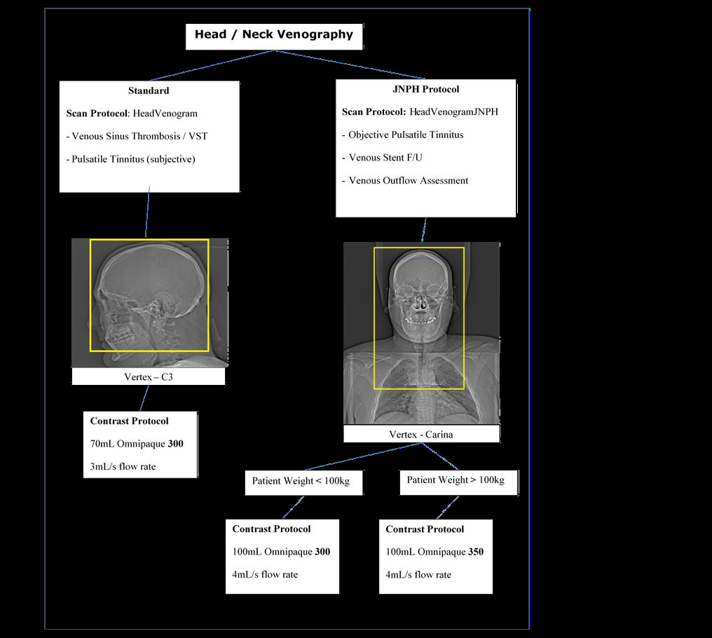
Venous sinus thrombosis
Pulsatile tinnitus (Subjective)
Protocol name: HeadVenogram
100mL
Vertex to C3
Idiopathic intracranial hypertension
Stents
Pulsatile tinnitus (Objective)
Specifically protocolled by JNPH
Protocol name: HeadVenogramJNPH
100mL
Vertex to Carina
13.8
Neuro Intervention
The Operator will be the Radiologist performing the procedure.
Exposures will be initiated using the foot pedal or scanner button (in-room) or control pad.
Table movement will be controlled i-Control (affixes to the side of the CT table).
Note: i-Control can be hard wired into the scanner in the event of wireless failure.
Preparation
CT Guided Nerve Root Injection Cervical
Prone position (or supine for Dr Scoffings)
White wedge pad for head support using the carbon fibre head rest (or flat end with pillow for Dr Scoffings)
Arms by the patient’s sides A theatre cap may be useful with patients that have long hair Topogram to be set to Craniocaudal
CT Guided Nerve Root Injection Lumbar
Prone position Flat table extension to be used Arms preferably by the patient’s head Select low dose as preference, based on operator discretion CT Guided Biopsy Bone / CT Guided Biopsy
Post contrast imaging may be useful and will be directed by the Radiologist prior to the procedure
Scan Process
A lateral Topogram will be performed over the area of interest. A scan volume will be placed over the level as identified by the Radiology.
Once the injection level is established, i-sequence will be performed by the Radiologist in the scan-room.
Protocol
IV
Imaging
Notes
CT Guided Nerve Root Injection Cervical
Protocol name: NRI_Cervical
CT Guided Nerve Root Injection Lumbar CT Guided Biopsy Bone
Protocol name: NRI_Lumbar
Protocol name: NRI_Lumbar_LD
13.9
Specialist Scanning
CT Head Perfusions (CTP):
Refer to the “Flowchart for acute Stroke Patients requiring CT Imaging”
Preparation
Position the patient supine with the head supported by the carbon fibre headrest.
The table extension and square head-pad can be used also if appropriate.
Using the Z-axis laser, ensure the patient’s median sagittal plane is aligned parallel.
Position the patient at the vertex using the internal laser light (Siemens).
Scan Process
The Topogram will be performed by default cranio-caudal with a lateral tube orientation.
Reconstruction
Reduce the field of view to allow a small air gap around the surface of the skin in all directions.
Please refer to Appendix 13 for colour maps
Contrast
Use the contrast injector to deliver the bolus of contrast
Protocol
IV
Imaging
Notes
Stroke Protocol
Protocol name: HeadPerfusion
50mL
Refer to the ‘Flowchart for Acute Stroke
Patients requiring CT Imaging’
Vasospasm
Protocol name: HeadPerfVasospasm
50mL
Note: First referral for vasospasm CTP will be accepted by the Radiographer.
Subsequent imaging referrals must be discussed with the Consultant Neuroradiologist
Neurosurgical referrals only
Refer to Appendix 15
13.10 Standard Paediatric Head Protocols
The following is a general guide for Neuro Band 7 Radiographers vetting requests to ensuring the correct protocol is applied.
If unsure, requests are to be vetted by a Consultant Neuro Radiologist.
Preparation
Position the patient supine with the head supported by the carbon fibre headrest.
Using the Z-axis laser, ensure the patient’s median sagittal plane is aligned parallel.
Ensure the head is tilted caudal to minimise gantry angulation and irradiation of the lens of the orbit.
Use immobilisation aids in the event of imaging non-compliant patients (side wedges, forehead strap)
Position the patient at the vertex using the internal laser light (Siemens).
Scan Process
The Topogram will be performed by default cranio-caudal with a lateral tube orientation.
The scan field outlined by the magenta box (Siemens) should align to the infraorbital-meatal line avoiding primary irradiation of
the lens of the orbit. Ensure the upper border of C1 to the Vertex is covered within the scan range. The scan will be performed by default caudo-cranial.
Reconstruction
Reduce the field of view to allow a small air gap around the surface of the skin.
Reconstruct the thin slice as acquired (without straightening). Reconstruct the 5mm (3D) reconstruction aligned to the subcallosal plane
Where reconstruction from RAW data cannot be performed, align the patient using the system MPR tool
Contrast (if required) Use either a hand or injector to deliver the bolus of contrast
The volume of contrast should amount to 1mL per kilo for a paediatric patient (not exceeding 50mL).
Protocol
IV
Imaging
Notes
Hydrocephalus
Headache ? haemorrhage
Meningitis
Post-surgical intervention
Trauma
Craniosynostosis
Protocol name: HeadRoutine3D_Paed
Non Contrast ? Metastasis with known primary
Abscess / Empyema
Protocol name: HeadContrast
1 mL per Kg*
Non contrast
Post contrast Hand/Pump inject 1mL per kilo (Scan at 3 minutes post contrast)
Not exceeding 50 mL
13.11 Operative Navigation (Paediatric Stealth)
Stealth compatible imaging requires contiguous thin (soft tissue kernel) slices with a zero gantry tilt.
Imaging is imported from PACS by the surgical team, to allow imaged guided surgical intervention.
Preparation
Position the patient supine with the head supported by the carbon fibre headrest.
Using the Z-axis laser, ensure the patient’s median sagittal plane is aligned parallel.
Ensure the head is not over tilted.
Ensure that the ears and nose are not touching anything or being clipped by anything.
Position the patient at the vertex using the internal laser light (Siemens).
Scan Process
The Topogram will be performed by default cranio-caudal with a lateral tube orientation.
The scan field outlined by the magenta box (Siemens) should have a zero gantry tilt.
Ensure the scan range covers the whole nose to just beyond the vertex. The scan will be performed by default caudo-cranial.
Reconstruction
Reduce the field of view to allow a small air gap around the surface of the skin.
Reconstruct the thin slice as acquired (without straightening). Reconstruct the 5mm (3D) reconstruction aligned to the subcallosal plane
Where reconstruction from RAW data cannot be performed, align the patient using the system MPR tool
Contrast (if required) Use either a hand or injector to deliver the bolus of contrast
The volume of contrast should amount to 1mL per kilo for a paediatric patient (not exceeding 50mL).
Protocol
IV
Imaging
Notes
Pre-Op Shunt Insertion/EVD
Protocol name: HeadStealth
Non Contrast
Scan from just above vertex to just below the nose. Very important to include the nose and above vertex for the stealth navigation system. The ears must not be touching anything or clipped.
Pre-Op for tumour removal
Pre-Op for abscess removal/Washout
Protocol name: HeadStealthContrast
1 mL per Kg*
Post contrast Hand/Pump inject 1mL per kilo (Scan at 3 minutes post contrast)
Not exceeding 50 mL
13.12
Standard Paediatric Spine Protocols
The following is a general guide for Neuro Band 7 Radiographers vetting requests to ensuring the correct protocol is applied.
If unsure, requests are to be vetted by a Consultant Neuro Radiologist.
Preparation
Position the patient supine with the head supported by the carbon fibre headrest when scanning the cervical spine or a pillow
for head support when scanning the thoracic or lumber spine.
When scanning the cervical spine ensure the arms are down by the patient’s side and raised if patient is able to do so, when
scanning the thoracic or lumber spine.
Using the Z-axis laser, ensure the patient’s spine is aligned to the median sagittal plane.
Position the patient with the internal laser light (Siemens) just above the ear for cervical spine and at the symphysis for lumber
spine.
Scan Process
The Topogram will be performed by default cranio-caudal for the cervical spine and caudo-cranial for the whole spine protocol
with a lateral tube orientation.
The scan field outlined by the magenta box must cover the desired area (Siemens).
Ensure the scan range for cervical spine covers from just above C1 down to T1 and for other areas of the spine ensure that
your scan range covers at least one level above and one below the asked for vertebra.
The scan will be performed by default cranio-caudal.
Reconstruction
Reduce the field of view to allow a small air gap around the surface of the skin.
Reconstruct the first recon box as acquired (without straightening). Then reconstruct the 3D thin sagittal and coronal reformats.
Where reconstruction from RAW data cannot be performed, align the patient using the system MPR tool
Protocol
IV
Imaging
Notes
Trauma
Pre or Post surgery
Protocol name: C-Spine
Non contrast
Scan from C1 to T1
Trauma
Scoliosis
Pre or Post surgery
Protocol name: Spine0_6yr
Non contrast
Scan at least one level above and one below the desired region.
13.13
Standard Paediatric Crainofacial Protocols
The following is a general guide for Neuro Band 7 Radiographers vetting requests to ensuring the correct protocol is applied.
If unsure, requests are to be vetted by a Consultant Neuro Radiologist.
Preparation
Position the patient supine with the head supported by the carbon fibre headrest.
Using the Z-axis laser, ensure the patient’s median sagittal plane is aligned parallel.
Ensure the head is not over tilted and in a neutral position. Position the patient at the vertex using the internal laser light (Siemens).
Scan Process
The Topogram will be performed by default cranio-caudal with a lateral tube orientation.
The scan field outlined by the magenta box must cover the desired area (Siemens)
For sinus scans ensure the scan range covers from the top of the frontal sinus to the bottom of the maxillary sinus. For orbit
scans ensure that just above and just below the whole orbit are covered and for inner ear scans please ensure the mastoid air
cells are all covered. The scan will be performed by default caudo-cranial.
Reconstruction
Reduce the field of view to allow a small air gap around the surface of the skin.
Reconstruct the thin slice as acquired (without straightening). Then reconstruct the 3D thin sagittal and coronal reformats.
Where reconstruction from RAW data cannot be performed, align the patient using the system MPR tool
Contrast (if required) Use either a hand or injector to deliver the bolus of contrast
The volume of contrast should amount to 1mL per kilo for a paediatric patient (not exceeding 50mL).
Protocol
IV
Imaging
Notes
Sinus
Sinusitis
Define bony anatomy for surgery
Protocol name: sinusesOrbit
Non Contrast
Scan from top of frontal sinus to bottom of maxillary sinus.
Tumour Evaluation
Protocol name: sinusesOrbit
1mL per Kg*
Non contrast (Check protocol on request as non contrast scan not always needed)
Contrast Hand/Pump inject 1mL per kilo
Please use sinusesOrbit
protocol and add the contrast used and volume.
Non contrast scan not always required please check protocol on request or with radiologist if unsure.
Orbits
Fractures
Protocol name: sinusesOrbits
Non contrast
Scan just above and just below the orbital socket.
Orbital Cellulitis/ Abscess
Tumour Evaluation
Protocol name: OrbitsContrast
1mL per Kg*
Non contrast (Not always needed check protocol on request)
Contrast Hand/Pump injection 1mL per kilo and scan 15 seconds after the end of the injection
Non contrast scan not always required please check protocol on request or with radiologist if unsure.
Please use OrbitsContrast protocol and add the contrast used and volume.
If child is able, ensure the eyes are closed. Create reformat
Appendix 17 .
Inner Ear
Semi-circular canal dehiscence
Cochlear Implants
Protocol name: InnerEar_UHR
Non Contrast
Scan to include all of the inner ear and mastoid air cells.
*Not exceeding 50mL
13.14
Standard Paediatric Vascular Protocols
The following is a general guide for Neuro Band 7 Radiographers vetting requests to ensuring the correct protocol is applied.
If unsure, requests are to be vetted by a Consultant Neuro Radiologist.
Preparation
Position the patient supine with the head supported by the carbon fibre headrest.
Using the Z-axis laser, ensure the patient’s median sagittal plane is aligned parallel.
Ensure the head is not over tilted and in a neutral position. Position the patient at the vertex using the internal laser light (Siemens).
Scan Process
The Topogram will be performed by default cranio-caudal with a lateral tube orientation.
The scan field outlined by the magenta box must cover the desired area (Siemens)
For head angio scans ensure the scan range covers from the vertex to C3. For neck angio scans ensure that the scan range
covers from the vertex to carina. For venograms ensure that the scan range covers from vertex to C3 and for ENT neck scans
ensure that the scan range covers from base of skull to the arch.
For head & neck angios as well as venograms the scan will be performed by default caudo-cranial. However for ENT neck
scans they are performed cranio-caudal by default.
Reconstruction
Reduce the field of view to allow a small air gap around the surface of the skin.
Reconstruct the thin slice as acquired (without straightening). Then reconstruct the 3D thin sagittal and coronal reformats.
Where reconstruction from RAW data cannot be performed, align the patient using the system MPR tool
Contrast (if required) Use either a hand or injector to deliver the bolus of contrast
The volume of contrast should amount to 1mL or 1.5mL per kilo for a paediatric patient (not exceeding 70mL).
Protocol
IV
Imaging
Notes
Aneurysm AVM
Vascular Abnormality
Protocol name: HeadAngio0-6yr
1mL per kilo*
Contrast
If pump injecting trigger scan at arch of aorta
If hand injecting the contrast volume. Inject, let the injecting person leave the scan room and scan immediately.
Scan from vertex to C3
Trigger off arch of aorta
Dissection
Vascular Abnormality
Protocol name: HeadNeckAngio0-6yr
1mL per kilo*
Contrast
If pump injecting trigger scan at arch of aorta
If hand injecting the contrast volume. Inject, let the injecting person leave the scan room and scan immediately.
Scan from vertex to carina
Trigger off arch of aorta
Sinus Thrombus
Protocol name: HeadVenogram0-6yr
1.5mL per kilo*
Contrast
If pump injecting 2 or 3mL per second is preferable and scan 10 seconds after the end of the injection.
If hand injecting the contrast volume. Inject the bolus and scan 10 seconds after the end of injection.
Scan from vertex to C3
Abscess
Tumour
Protocol name: ENTNeckContrast
1mL per Kilo*
Contrast
If pump injecting inject at 1mL per second and scan 15 seconds after the end of the injection.
If hand injecting the contrast volume. Inject the bolus and scan 15 seconds after the end of injection.
Scan from base of skull to arch
*Not exceeding 70mL
Paediatric Sedation and Vascular Access
14.1 Sedation
The need for sedation should be discussed at the time the request is accepted by a Consultant Paediatric Radiologist on a case by
case basis.
A 22G, blue cannula or 20G pink cannula, should be requested if the scan necessitates.
CT1, CT2, CT3 or CT4 should be used whenever possible in order to administer as lower dose as possible.
14.2 Intravenous Contrast Administration for Paediatric Patients
All paediatric contrast injections should be administered at 1, 2 or 3mL/sec.
Only peripheral cannulas with a bionector may be used to administer IV contrast.
Central access lines (PICC, Hickman or Central Lines) are NOT permitted.
Hand Injections
A hand injection is preferred if:
The child is under 10kgs.
Small cannula (yellow) in situ.
Pump Injections
If the child has a 22G, blue cannula or 20G pink cannula, in situ the pump can be used above 10kgs
If using the pump a Radiologist or a Radiographer who has completed Paediatric Injection Competencies should check the line using
the Trusts ANTT, Hand Hygiene Policy, and Administration of Medicines policy.
Pump injections must be supervised in the scanning room whilst the injection is being administered. The exception to this is a bolus
tracked scan or if X-rays are in process during injection.
Standard paediatric protocols
Radiology registrars and Band 7 CT radiographers can accept and protocol paediatric CT requests.
References
1 Kambadakone AR et al. Abdom Radiol (NY). 2018 Jan;43(1):56-74. doi: 10.1007/s00261-017-1325-y.
www.eoetraumanetwork.nhs.uk/tempo
16 Associated documents
ANTT Hand Hygiene Policy Administration of Medicines policy
Equality and diversity statement
This document complies with the Cambridge University Hospitals NHS Foundation Trust service equality and diversity statement.
Disclaimer
It is your responsibility to check against the electronic library that this printed out copy is the most recent issue of this document.
Document management
The table below will be completed by the Trust documents team:
Approved by:
Kevin Mortimer
Approval date:
12 January 2022 JDTC approval date:
Owning department: CT Scanning - Imaging
Author(s):
David Bowden/Kevin Mortimer/Daniel Scoffings/David Biddle/Joanne
Loughnane/Claire Stanford
Pharmacist:
File name:
CT Scanning Protocol Document
Supersedes:
Version 13.0
Version number:
Version 14.0
Local reference:
Document ID:
Appendix 1 Contrast, Dose & Injection Rates vs Bodyweight
Omnipaque 300
Omnipaque 350
Weight
(kgs)
Omni 300
(mL)
Flow Rate
(mL/s)
Weight
(kgs)
Omni 300
(mL)
Flow Rate
(mL/s)
4.0 4.0 4.0 4.0 4.0 4.0 4.0 4.0 4.0 4.0 4.0 4.0 4.0 4.0 4.0 4.0 4.0 4.0 4.0 4.0 4.0 4.0 4.0 4.0 4.0 4.0 4.0 4.0 4.0 4.0 4.0 4.0 4.0 4.0 4.0 4.0 4.0 4.0 4.0 4.0 4.0 4.0 4.0 4.0 4.0 4.0 4.0 4.0 4.0 4.0 4.0 4.0 4.0 4.0 4.0 4.0 4.1 4.0 4.1 4.0 4.2 4.0 4.3 4.0 4.3 4.0 4.4 4.0 4.4 4.0 4.5 4.0 4.6 4.0 4.6 4.0 4.7 4.0 4.7 4.0 4.8 4.0 4.9 4.1 4.9 4.1 5.0 4.2 5.0 4.2 5.1 4.3 5.2 4.3 5.2 4.4
Omnipaque 300
Omnipaque 350
Weight
(kgs)
Omni 300
(mL)
Flow Rate
(mL/s)
Weight
(kgs)
Omni 300
(mL)
Flow Rate
(mL/s)
5.3 4.4 5.3 4.5 5.4 4.5 5.5 4.6 5.5 4.6 5.4 4.7 5.4 4.7 5.74 4.8 5.8 4.8 5.8 4.9 5.9 4.9 5.9 5.0 6.0 5.0 6.1 5.1 6.1 5.1 6.2 5.2 6.2 5.2 6.3 5.3 6.4 5.3 6.4 5.4 6.5 5.4 6.5 5.5 6.6 5.5 6.7 5.6 5.6 5.7 5.7 5.8 5.8 5.9 5.9 6.0 6.0 6.1 6.1 6.2 6.2 6.3 6.3 6.4 6.4 6.5 6.5 6.6 6.6 6.7
Appendix 2 DIEP Post-Processing Reconstruction Guide
Reproduce the following for deep inferior epigastric perforator flap pre-operative
breast reconstruction planning.
Use the ‘Arterial Phase 1.0/0.7 B20f’ reconstruction to construct VRT in the 3D
card, or Syngovia®.
For Coronal Reformat:
Click / highlight axial view
Click ‘Parallel Ranges’ then click the horizontal ranges
Find the DIEP (Inferior Epigastric Artery)
Set the lines parallel to each other
Cover the anterior abdomen to both iliac arteries
Highlight the 4th box and click ‘MIP Thin’ [^^TYPE^^]
On ‘parallel ranges’ set up – image thickness = 35.0mm
Distance between images = 5.0mm (Approximately 26 images)
Click START
Then click SAVE AS then type Coronal MIP’s
For Axial Reformat:
On axial view, click the free mode, make sure that the green line is parallel to the
Inferior Epigastric Artery
Highlight the 2nd box (Coronal View)
Click ‘Parallel Ranges’ then click the horizontal ranges
Find the DIEP (Inferior Epigastric Artery)
Cover from the kidneys to the femoral head
Highlight the 4th box, and click ‘MIP Thin’ [^^TYPE^^]
On ‘parallel ranges’ set up – image thickness = 35.0mm
Distance between images = 5.0mm (Approximately 55 images)
Click START
Then click SAVE AS then type Axial MIP’s
Appendix 3 CT Thoracic Aorta aneurysm surveillance protocolling flow
chart
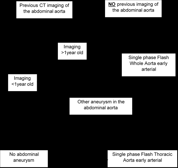
Appendix 4 CT AAA surveillance protocolling flow chart
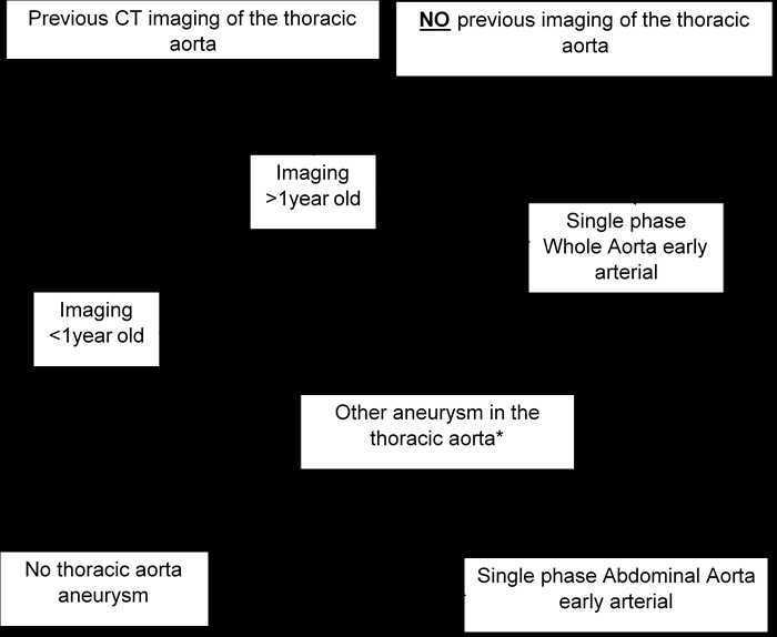
Appendix 5 Bilateral Arm Injection Guide
2-Pump Method
Patient is placed on the scanning table with a minimum of 2, 22G (Blue) cannulas in the
ACF’s.
On the first pump in the scanning room select the patients name and enter the weight and
cannula type as normal. Select the 2.0ml/sec protocol and amend the volume to 50mls.
A second mobile pump is borrowed from another scanner and an anonymous patient is
selected and the same protocol is selected and amended as above.
On the scanner select the SVC_Obstruction protocol. (Includes a 25second delay chest and
70second delay chest)
Both pumps in the scanning room and the scan should be started at the same time.
Hand Injection Method
Patient is placed on the scanning table with a minimum of 2, 22G (Blue) cannulas in the
ACF’s.
On the first pump in the scanning room select the patients name and enter the weight and
cannula type as normal. Select the 2.0ml/sec protocol and amend the volume to 60mls.
20mls of contrast should be drawn up.
On the scanner select the SVC_Obstruction protocol. (Includes a 25second delay chest and
70second delay chest)
The pump in the scanning room, the Radiographer hand injecting and the scan should be
started at the same time.
The radiographer hand injecting needs to pace the administration of contrast to last as long
as possible but ensuring all contrast is used before they leave the room at the last minute.
(Contrast needs to be in the vessels near the shoulder therefore injecting too quickly before
the scan starts means we will miss the contrast)
Appendix 6 CT Enterography Proceedure
Check all requests with Consultant GI Radiologist.
Ensure the patient has been starved for 6 hours prior to scan. The patient should arrive 1.5 hours before their appointment time. On arrival make up a solution of Kleenprep® powder (found in GG cupboard in reception) in 1L of water. Add cordial if preferred by patient.
The patient is to drink 0.5L of the Kleenprep® solution over 15mins, followed by the
next 0.5L over the next 15mins.
Once the patient has consumed the Kleenprep® solution they must be given 1L of
water. Again add cordial if required. Again 0.5L to be drunk over 15mins and the rest over the following 15mins. The scan should take place 1 hour from the START of drinking the Kleenprep®
solution; therefore, ideally cannulate the patient before entering the scan room.
Once in the scanning room the patient is to be given 1mL of Buscopan, one final cup
of water and must be laid on their right hand side for a couple of minutes. Perform a supine portal Abdo/Pelvis scan. Label the reconstructions as
‘Enterography’ and ensure the Kleenprep® details are recorded on the Notes section
of the patients’ Epic examination entry so that it is reported by the appropriate
Radiologist. IF THE PATIENT HAS HAD BOWEL REMOVED PREVIOUSLY OR STARTS TO HAVE DIARRHOEA DURING/AFTER KLEENPREP BRING THE SCAN TIME FORWARD 10- 15MINS.
Document any problems with drinking times or list unfinished drinks on under the
Notes section of the patients’ Epic examination entry.
Immediate side effects include:
Abdominal distension and cramps; diarrhoea; bloating
Appendix 7 Orthopaedic Reconstruction of Pelvic & Hip Fractures
A. Load thin 1.0/0.6 soft tissue images of pelvis or extremity into InSpace / 3D
Card / Syngovia®
B. Access the ‘ Musculoskeletal ’ folder and apply the ‘ Transparent bone 2 ’
window/VRT construction, pictured as a skull, or implant transparent bone window. C. Straighten up the image if patient was rotated on the acquisition CT Scans.
D. Press the Radial Range button, this can be found under the ‘tools’ tab, at
the bottom right of the screen (image of a silhouetted head with a spoke wheel overlaid): E. A table will appear where angles of the recons can be manipulated. Total angle should be set at 360° F. Step angle at 10° G. Number of steps is automatic
H. Set the axis of recons to HF
I. Press start, save images
J. Set the axis of recons to LR
K. Press start, save images, send to PACS L. Repeat all of the above with an ‘Opaque Vessels’ window / VRT construction.
This can be found in the ‘Neuro’ folder of windows / VRT constructs.
N.B some windowing may be required to remove the soft tissue and scanning
table.
If reconstructing using Syngovia® please refer to guidelines on CT network

Any previous CT imaging from
vertex of the head to below
both Knees?
Yes
No
If a CT Skeletal
Survey has been
performed within
the last 6 months:
NOT for repeat
imaging.
Case must be
discussed with
MSK Radiologist
If CT Imaging
performed within
the last 3 months:
Complete staging
with
X-Ray.
If unsure discuss
case with
MSK Radiologist
Proceed to
CT Skeletal
Survey
If clinically
justified.
If unsure discuss
case with
MSK Radiologist
Appendix 8 Skeletal Survey Protocol
Symptomatic BCSP
Clinical details:
CIBH + FIT weight loss LGI pathway failed/unsuitable for colonoscopy BCSP means +FIT
Must be unsuitable for or had a failed colonoscopy.
Patient choice is NOT a justification for CTC for 1 st investigation
Recent colonoscopy?
No
Yes
Yes
Recent colonoscopy?
No
Biopsy/polypectomy/EMR (endoscopic mucosal resection)?
Yes
No for BCSP
Protocol as BCSP:
Colon prep NO IV contrast < 1 week CP
Check allergies as normal
Protocol as symptomatic:
Colon prep IV contrast – portal < 1 week CP
Check creatinine/eGFR as normal
Check allergies as normal
No for symptomatic
Biopsy
NO delay required.
Protocol as for symptomatic or BCSP but with a low dose supine acquisition before insufflation (this is to check for perforation) (Low dose acquisition is required < 2 weeks for a *left sided biopsy and < 4 weeks for *right sided)
Polypectomy/EMR/ESD (endoscopic submucosal resection)
DELAY is required.
Protocol as for symptomatic or BCSP but with the following:
2 week delay for *left sided
4 week delay for *right sided
Symptomatic or BCSP request? * Left sided is rectum to mid transverse * Right sided is mid transverse to caecum
Appendix 9 CTC Protocolling Flow Chart
Appendix 10 CTC After Intervention at Coloscopy Policy
Following endoscopic mucosal biopsy ONLY
No necessary delay following colonoscopy.
Do ultralow / low dose supine CT abdomen / pelvis prior to insertion of rectal tube and
review.
Following polypectomy or combined biopsy / polypectomy procedures or EMR
If left-sided polypectomy, two week delay prior to CTC. If right-sided polypectomy, four week delay.
If EMR (endoscopic mucosal resection) or ESD (endoscopic submucosal dissection), four
week delay.
No need for pre-insufflation CT in cases where more than two weeks has elapsed post
procedure.
Views
Right colon – caecum to mid transverse colon Left colon – mid transverse colon to rectum
Review
Each scan must be reviewed on “lung windows” before proceeding to the next stage to
check for free air.
Suspected perforation
If perforation is suspected the insufflator should be turned off and the duty Radiologist
informed immediately. Refer to Perforation of the Large Bowel during CT Colonography Policy.
Appendix 11 CT Head Imaging Technique
Align the scan range to avoid the lens
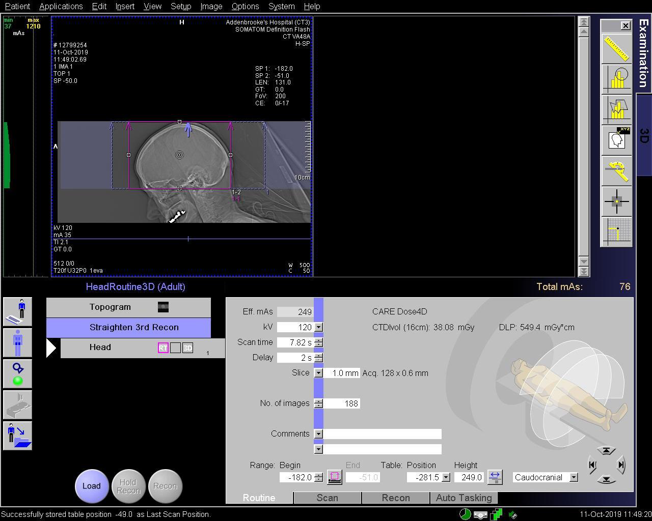
Start the 1 st and 2 nd reconstruction which are both thin slice
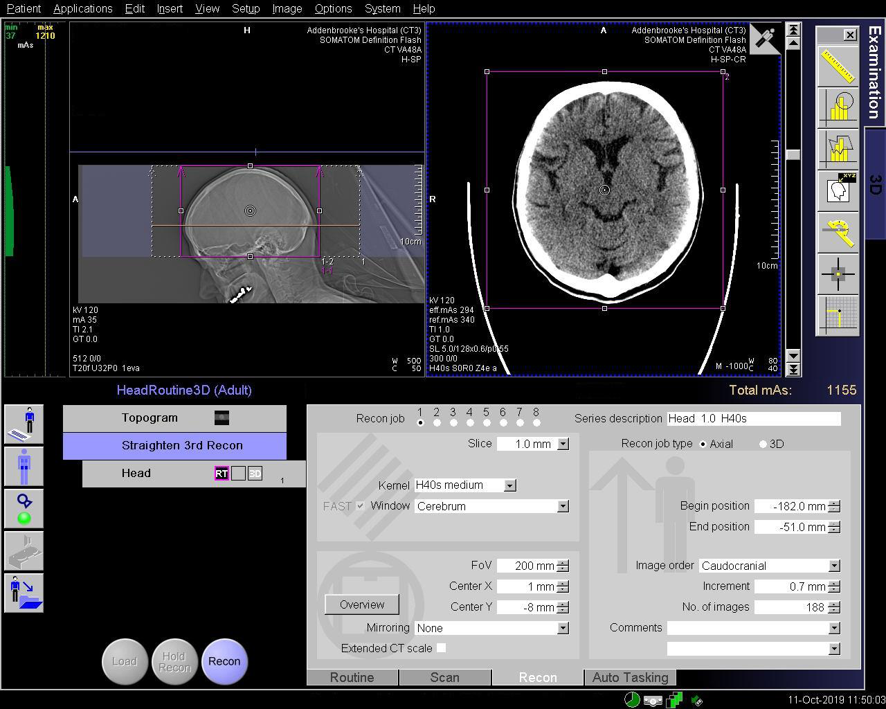
Once the 1 st reconstruction has completed, click on the 3 rd reconstruction.
Change the “Planning Base” to “Head 1.0 H40s” (or equivalent) indicated in yellow. The MRP will change into high quality.
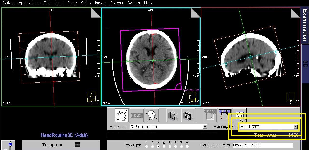
Straighten the head (FAST 3D auto correction may be enabled on some scanners, all a few seconds for this to complete)
Note: auto correction will only apply once the Planning Base has been updated to the thin slice reconstruction.
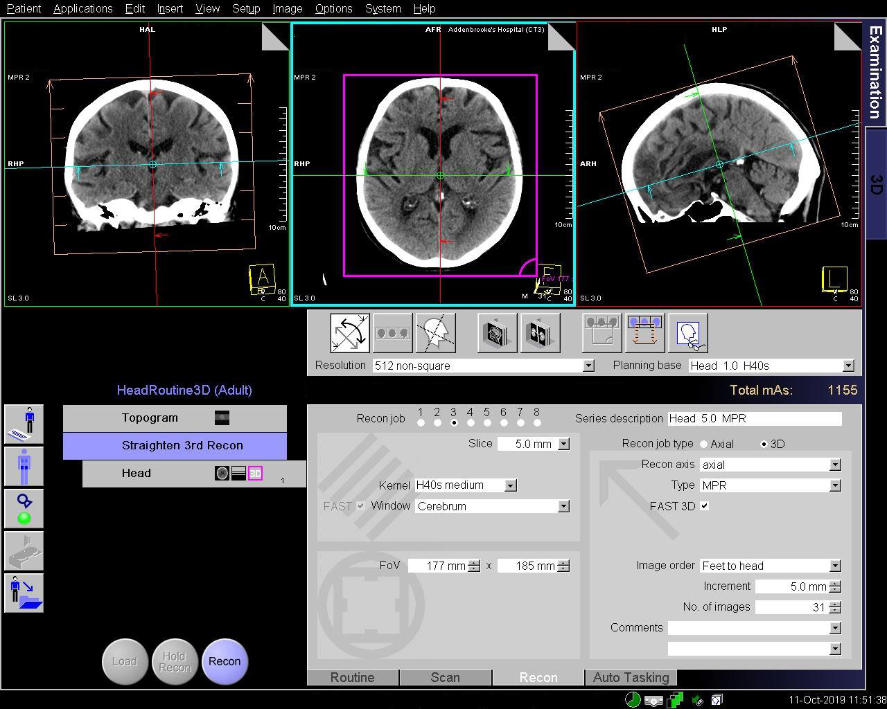
Navigate to the midline and tilt the range using the blue line on the SAGITTAL image. Align the blue line across the inferior
genu and splenium of the corpus callosum.
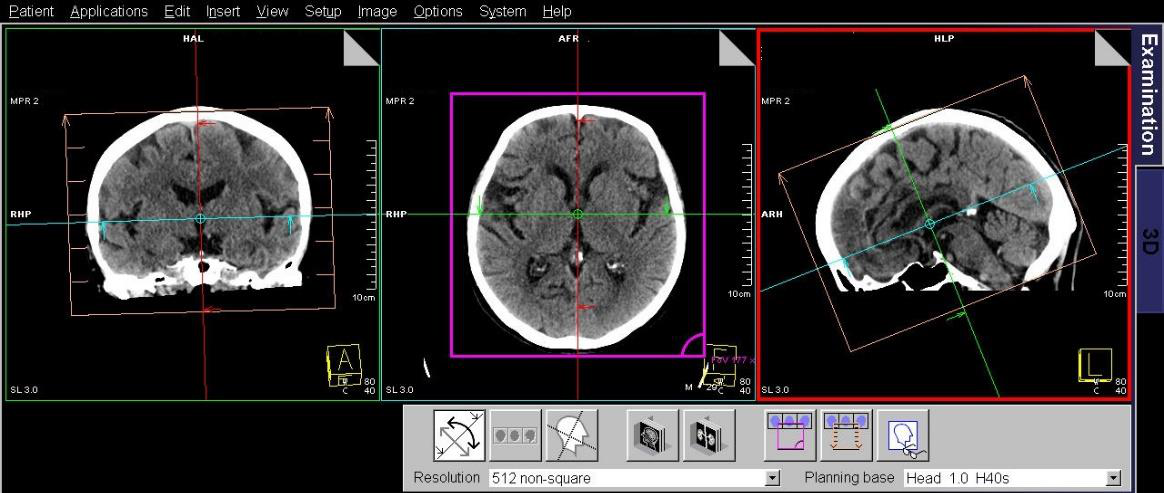
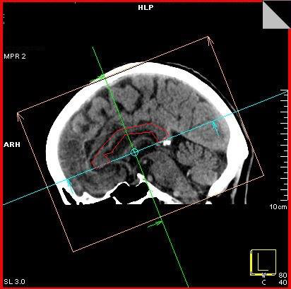
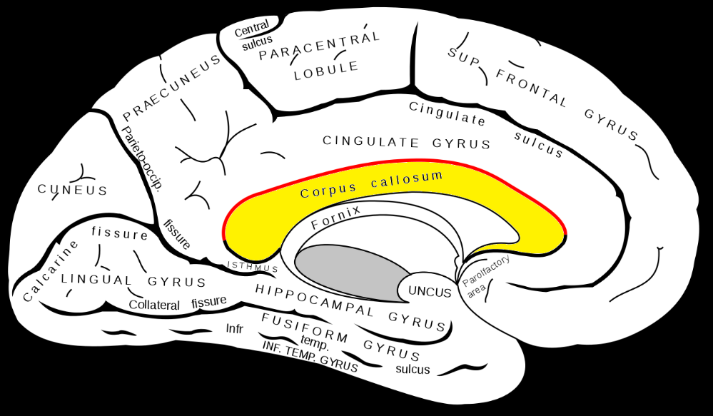
Appendix 12 Dementia Reformats
Coronal and sagittal reformats (on-scanner post-processing)
Load 1.0 mm H30/J30 series into the 3D card.
Straighten up if necessary using the dashed coloured lines.
On the axial box, offset the red vertical line so it passes through a temporal horn of the lateral ventricles (Fig. 1).
Now go to the sagittal box (now offset) and angle the blue line so that it is parallel to the long axis of the hippocampus, which
lies in the inferior part of the temporal horn. You should see the temporal horn stretch out on the axial image (Fig 1).
When you are happy with the angulations return to the axial box and select parallel ranges.
Set to contiguous 3 mm slices.
Do not angle the parallel ranges (Fig 2).
Do the same with sagittal parallel ranges (Fig. 3).
‘Save as’ after each set and name accordingly.


Fig. 1
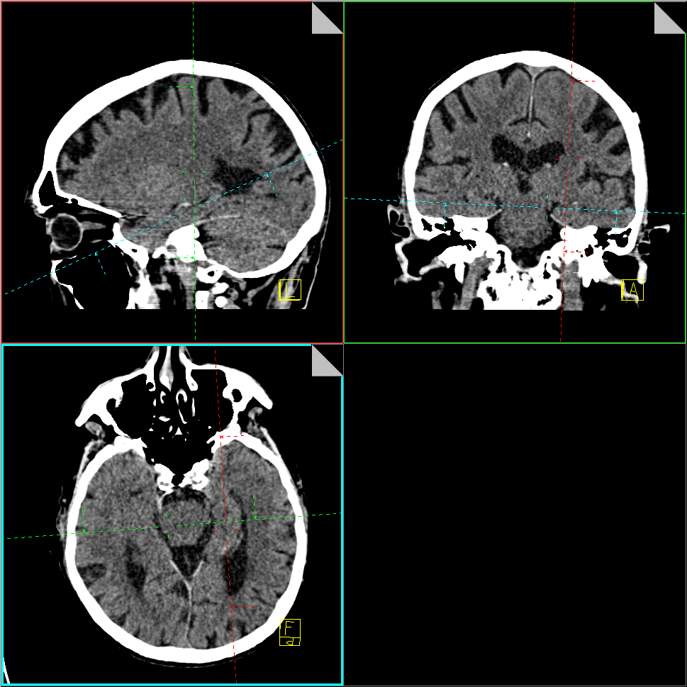
Fig. 2
Fig. 3
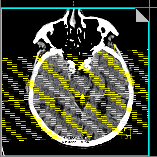
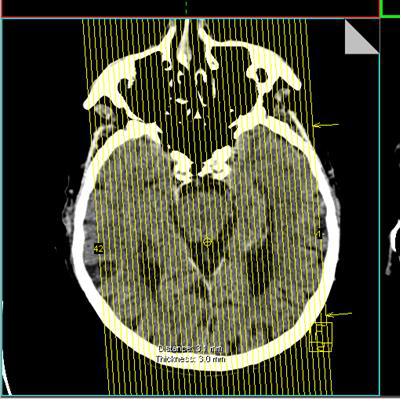
Appendix 13 Brain Perfusion Maps
The following applies to on-scanner software only
Post processing is only available on CT2 (Siemens Definition AS+)
Load the scan data “VPCT DynMulti4D 10.0 H20f” into “VPCT Neuro” card on the Workstation.
The Organ selection box will display and the preferred preset is “Auto Stoke MTT”. This option provides the best method to
automate the processing of data.
There are 4 steps in the process of analysis. The software will proceed through each automatically and will only halt if it
requires user input. If the process halts, resolve the issue and click on the blue tick to proceed. The steps are as follows:
Step 1: Motion Correction
The yellow boxes will appear next to the vertical scroll bar on the right at the levels where there is
movement detected. You can select each one by the “Next/Previous Critical Time” Point button. The centre button will remove the images at the current time point.

Step 2: Segmentation
This step usually requires no intervention. Click on the blue tick to proceed to the next step.
Step 3: Vessels
Check the software has correctly located the midline.
The software will attempt to find the best region of interest for an arterial and venous vessel.
If the curves on the graph do not represent a bell shape then you will need to manually draw a region of interest.
The best region for the arterial input function is the A2 segment of the anterior cerebral artery, which is what the
icon indicates. Keep trying to achieve a good bell curve on the arterial and venous lines.
The threshold must be adjusted to include the blood vessels only, for exclusion from the calculation.
Count the red squares to the peak of the curve which will correspond to the strongest arterial “DynMulti4D 1.5 H20f xx ” series
for angiographic reconstructions (Unless you have removed time points from the series due to motion!).
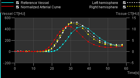
Step 4: Normalisation
The software will normalise the data set.
Click on the calculator.
Once the perfusion maps have been produced, click on “Edit” and then “Select series” from the menu bar.
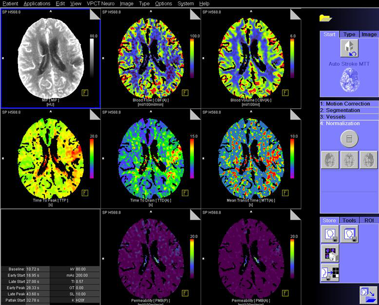
To save click on “ Save RGB”. Ensure the data below is sent to PACS
CT Brain Perfusion Post Processing using Syngo.Via
Launch Syngo.Via Client using the icon on the Desktop of a Standard Trust Computer
Login using the Trust Computer username and password
Enter the MRN into the Patient Browser (Red arrows)


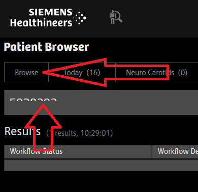
Right click the study and select “Open With”, “CT Neuro Perfusion”
Verify the initial output by checking that you have “bell” curves in the TAC chart.
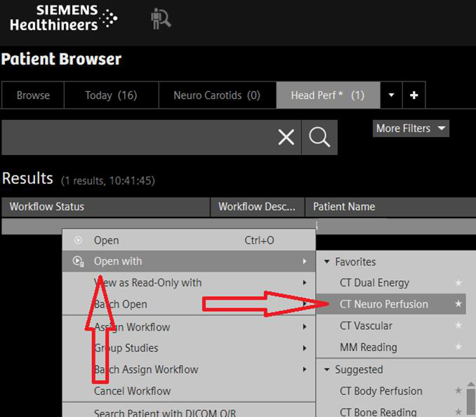
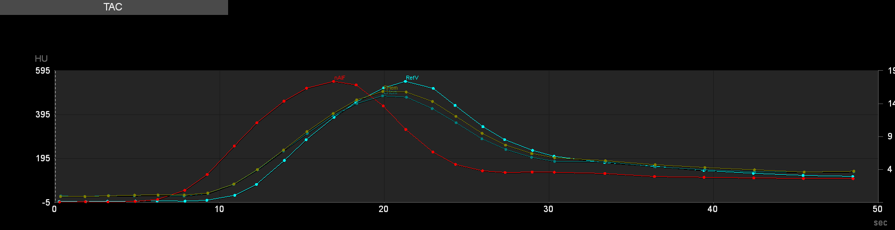
Confirm the calculations by clicking “confirm! (RED arrow)
Once confirmed, to make further adjustments you must reset the workflow.
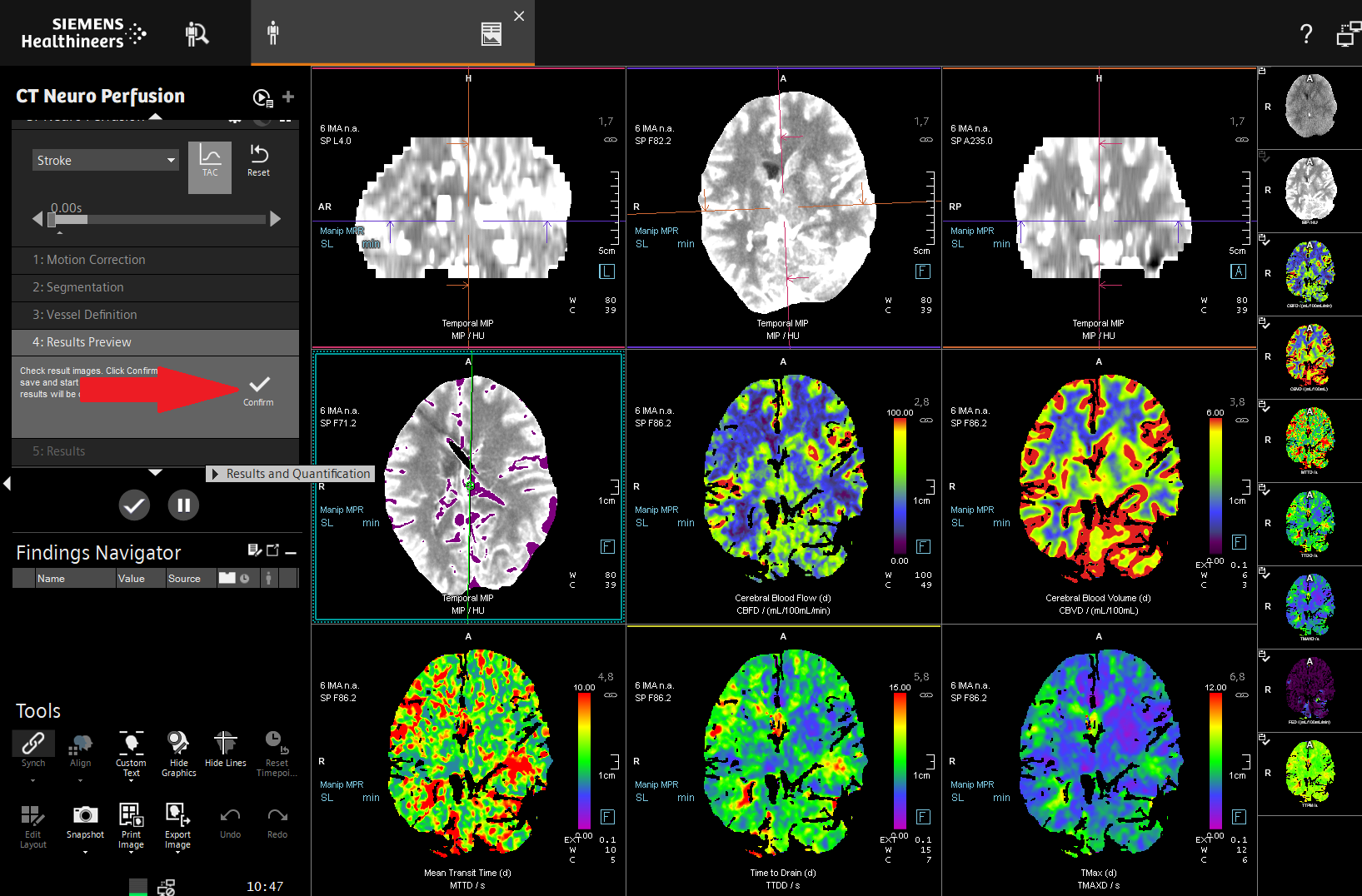
To archive the results to PACS, click on the tick (RED ARROW)
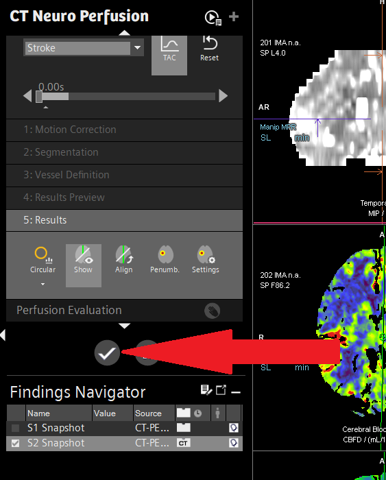
Appendix 14 Max-Fax Facial Bones and Mandible reconstruction
Use Syngo.Via to perform volume rendered reformats. The following will guide you through using Syngo.Via.
Search for the patient using either name or MRN
The workflow should be “MM Reading”, if the field is blank, right click and “Open With”, selecting MM reading.
Ensure the soft tissue volume is loaded. To load an alternative volume, drag the series into the workspace

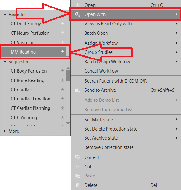
Select ‘Cinematic VRT ‘ by hovering the curser over the bottom left icon on the image.
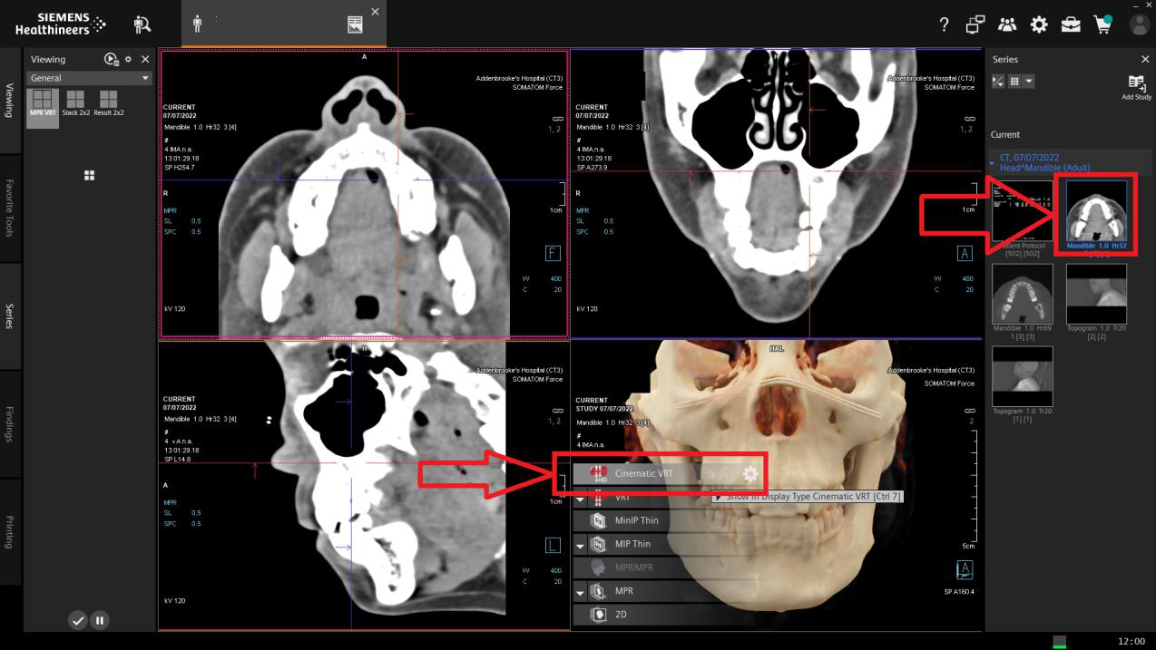
Double click the VRT image to view the whole screen
Note:
Right mouse (hold click) rotates the image
Left clicking the orientation cube (yellow highlight) will snap to the view indicated.
To save images, press ‘S’ on the keyboard.
Saved images will appear as results in the series column on the right-hand-side.
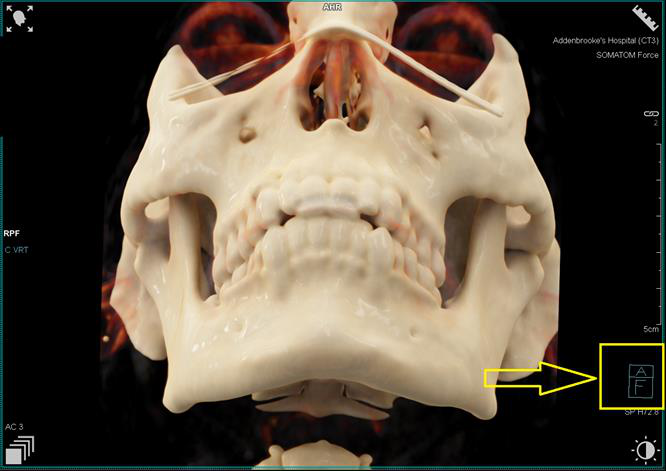
Once finished, ‘Save and Send’ by clicking the tick (yellow highlight) or closing the patient
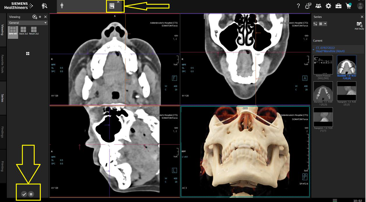
Appendix 15 Sinus Reformats
1.
Coronal and Sagittal reconstructions should be performed whilst in the Examination Card (Siemens) wherever possible.
If this is not available, Syngo.Via or an alternative should be used, using the sharp kernel bone volume only.
2.
If necessary straighten the images, prior to assessing landmarks for the reconstruction plane.
Coronal
Baseline: Perpendicular to the hard palate.
Coverage: Front of nose to the back of the sphenoid sinus.
Direction: Anterior to posterior
Slice thickness: 1mm
Sagittal
Baseline: Median sagittal plane
Coverage: Ethmoid sinus
Direction: Left to right
Slice thickness: 1mm 3.
Ensure any saved imaging is sent to PACS.
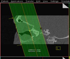
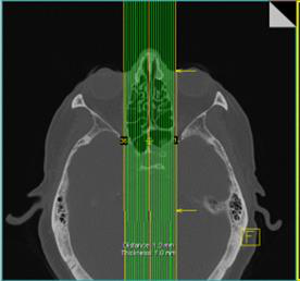
Appendix 16 Spine Reformats
Coronal and Sagittal reconstructions should be performed whilst in the Examination Card (Siemens) wherever possible. If this is
not available, Syngo.Via or alternative should be used, using the sharp kernel bone volume only.
If necessary straighten the images, prior to assessing landmarks for the reconstruction plane.
Coronal
Baseline: Parallel to the long axis of the spine
Coverage: Front vertebral body to end of spinous process
Direction: Anterior to posterior
Slice thickness: 2mm
Sagittal
Baseline: Median sagittal plane
Coverage: Lateral aspects of the bony spine
Direction: Left to right
Slice thickness: 2mm
Note
Depending on the clinical information and why you are scanning the spine sometimes soft tissue reconstructions may also be
needed. For example sagittal soft tissue recons for degenerative spines are desirable.
If scanning the spine as a myelogram study, coronal and sagittal recons (both bony and soft tissue) must be completed.
Ensure any saved imaging is sent to PACS
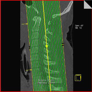
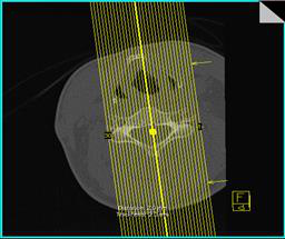
Appendix 17 Orbit Reformats
Load the 1mm thin H30 soft tissue or 1mm thin H70 bony reconstructions of the orbits into the 3D card depending on what you
are scanning for.
If necessary straighten the images.
Using the sagittal image by clicking on it to highlight the box surrounding it, place your recon lines on by clicking on the parallel
ranges icon on the right hand side of the screen.
Place your lines on the axial image starting from the front of the orbits and dragging your lines to the back of the optic nerve.
These recons must be reconstructed in 3mm width slices.
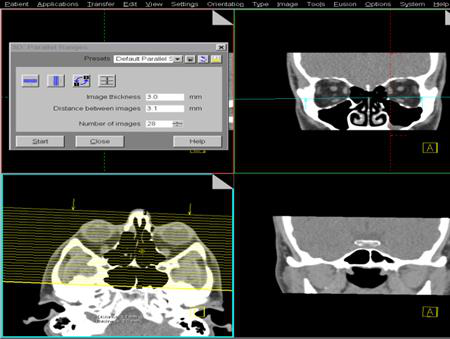

Click start, save images.
Sometimes bony coronal reconstruction will be needed, for example when looking for fractures.
Sagittal Orbit reconstruction may also sometimes be of value; again these images should be reconstructed in 3mm width slices.
To achieve this place your recon lines on the axial image parallel to the optic nerve and drag from left to right. These should be
done if soft tissue pathologies are found or fractures by using the bony recon images.
This time, place your parallel ranges lines on the axial image starting from the left and drag to the right creating some sagittal
images.
Click start, save images
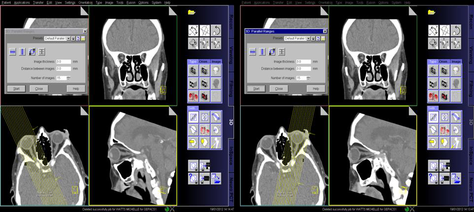
If your axial images were not straight it may be worth creating and saving a straightened set. This time use the sagittal image to
plan from. Place your parallel ranges lines parallel to the optic nerve and drag to cover the whole of the orbital area.
These must again be in 3mm width slices.
Click start, save images.
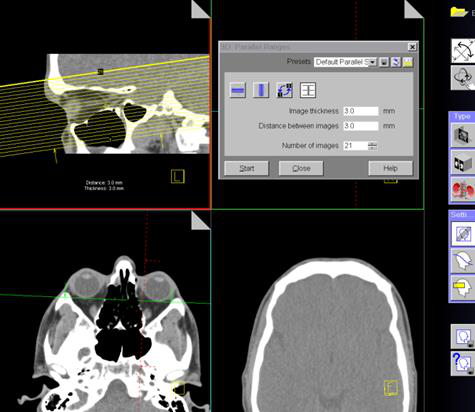
Appendix 18 Vasospasm Imaging
Cerebral Vasospasm is the vasoconstriction of arterial vessels that can lead to brain ischaemia and haemorrhage. There is
specific pathway for treating patients with Vasospasm called ‘Triple H Therapy’
Induced Hypertension, Hypervolemia and Haemodilution form the ‘Triple H Therapy’
Imaging can be important with the diagnosis of vasospasm by defining defects within the pattern of cerebral perfusion
Scanning Protocol Methodology
The perfusion scan technique allows a quick and reliable assessment of the type and extent of perfusion disturbances in the brain.
Perfusion CT is a software application based on dynamic CT images acquired directly after contrast injection.
Perfusion CT analyses the increase of Hounsfield numbers caused by iodine enhancement, which is relatively small and appears
against a high background noise.
Image quality depends on iodine enhancement/noise ratio. Increasing the mAs will reduce the noise; however, will increase the
dose of radiation. Thick slices will decrease the noise and a compromise between this and the mAs is met.
High atomic number materials such as iodine show higher CT numbers at lower kV settings therefore 80 kV is used to exaggerate
this.
A fast rotation time of 1 sec or less will be used to achieve good temporal resolution therefore the accurate assessment of the
contrast bolus can be made pixel by pixel.
The contrast bolus will be given a saline chaser to optimize the contrast enhancement.
The extracted CTA will allow the assessment of the vessels within the head
Scanning Workflow
A non-contrast brain should always be performed in the first instance.
Ensure all imaged data is correctly archived to the PACS system and the patient’s attendance finalised on the RADIANT system
with the correct code.
Preparation
The multi-angle carbon fibre headrest should be used as gantry tilt is not available.
The patient will be cannulated preferably in the antecubital fossa.
Cannula no smaller than 20G, injection rate 5mL/sec
When appropriate, the patient must be reassured and put at ease due to the length of the scan, very rapid hot flush (table motion).
The dual head pump injector and will contain 50mL contrast and 50mL saline.
The injection rate is the same for both syringes.
Technique
Topogram
Vertex to C3 Ensure the patient’s head is isocentred within the Gantry
CTH
Supraorbitomeatal baseline
Ensure the patient’s head is central within the blue shaded columns either side
Scan range should include from Vertex down to the body of C1
A second reconstruction should be added to provide 5mm contiguous slices in the axial plane if the patient is not
aligned straight.
CTP
The perfusion scan range is 10cm
Its placement on the Topogram should be sufficient to provide maximum coverage.
As a guide, align the bottom pink line to the approximate inferior border of the pituitary fossa and verify your position
using the non-contrast scan.
The second reconstruction provides the 4D Angio and should be processed as described further in this document
Do Not Reconstruct the Second Box Until You Have Processed the Perfusion
Post Processing
As per Brain Perfusion workflow in Appendix 10
Extract CTA
On the Perfusion Card or the ‘Snapshot’ saved, look for the earliest peak on the Time Attenuation Curve (TAC)
2. To check, you can click on the two vertical white lines as shown in Fig. 2. This
will place a white line on the TAC
Each complete table movement will correspond to reconstructable range of 1.5s, therefore in the example, 20seconds is not
achievable directly. In this case; the Begin time should be 19.5 seconds and End time 21 seconds.
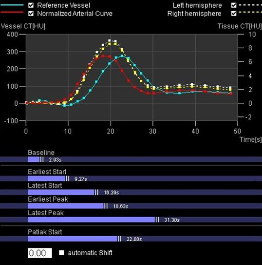
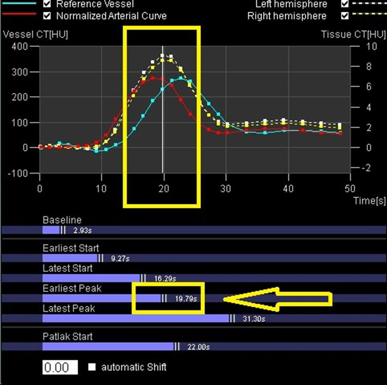
This will produce one series called “VPCT DynMulti 0.6 H20f 1”
ARCHIVE THIS TO PACS MANUALLY
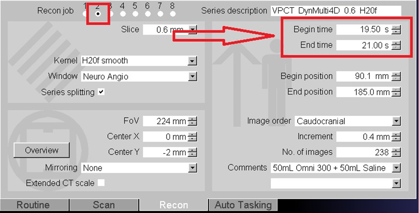

Appendix 19 Temporal Bone Reformats
Reference AJNR 2019
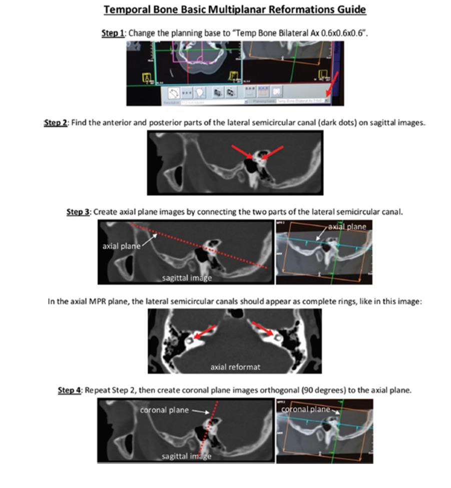
Appendix 20 Cerebral Venography